Eureka AIR delivers breakthrough ideas for toughest innovation challenges, trusted by R&D personnel around the world.

Method for recognizing circuit switching on and failures through specific short window integral value of directional traveling waves

A technology of short-window integration and directional traveling waves, which is applied in the direction of the fault location, can solve the problems that the protection cannot operate correctly, the fault is difficult to identify, and the circuit breaker is not considered to be closed at the same time.

Active Publication Date: 2015-03-25
KUNMING UNIV OF SCI & TECH
View PDF5 Cites 19 Cited by
  • Summary
  • Abstract
  • Description
  • Claims
  • Application Information

AI Technical Summary

Problems solved by technology

However, these traveling wave characteristics analysis and protection principles are mainly aimed at the failure of the normal operating line. When the closing operation is performed, these protections will not operate correctly. Therefore, further research on the identification method from closing to fault is needed.
In the early days, traveling wave polarity comparison type directional protection was used to identify the closing on the fault line. The method is similar to a simple traveling wave ranging method. It is difficult to identify the fault near the end of the line, and the forward and reverse traveling waves are in asymmetrical faults. The problem of the same polarity in the situation, and the failure to consider the problem of the circuit breaker not being closed at the same time

Method used


Image

  • Method for recognizing circuit switching on and failures through specific short window integral value of directional traveling waves
  • Method for recognizing circuit switching on and failures through specific short window integral value of directional traveling waves
  • Method for recognizing circuit switching on and failures through specific short window integral value of directional traveling waves

Examples


Embodiment 1 Embodiment 1

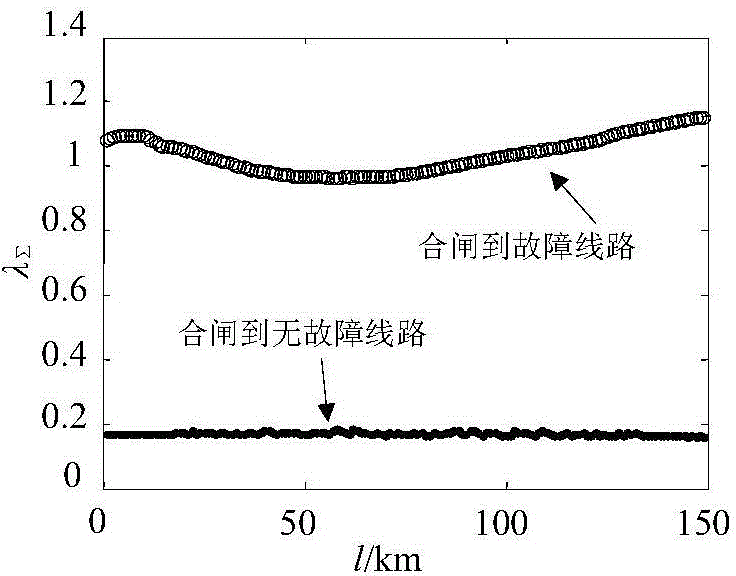
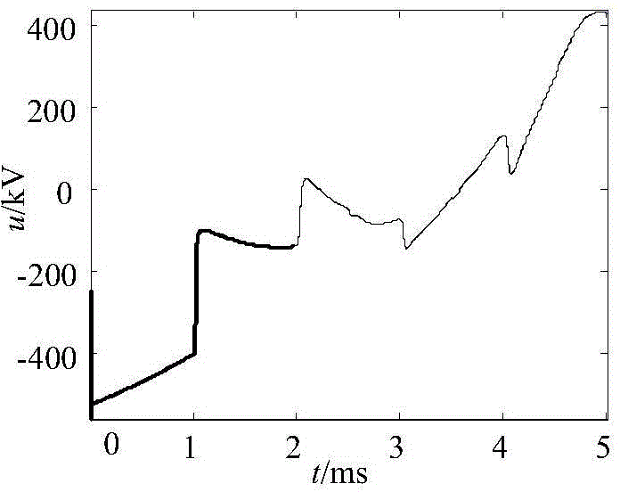
[0041] Embodiment 1 Embodiment 1: as figure 1 The simulation system model of 500kV transmission line shown, the line to be protected is MN, and the line length is L PM = 150km, L MN = 150km, L NQ =220km, the sampling rate is 1MHz. Assume that the A-phase circuit breaker at the N-end of the protected line is in the disconnected state, and the A-phase circuit breaker at the M-end of the protected line’s measurement end performs the closing operation, assuming that there is no fault in the line MN and an AG metallic ground fault occurs 149km away from the M-end , the transition resistance is 0Ω, and the initial phase angle is 90°.

[0042] After a single-phase ground fault occurs on the protected line, the faulty phase is disconnected. At this time, the circuit breaker of the faulty phase at the M terminal of the protected line performs the closing operation, and the circuit breaker at the N terminal at the other end of the protected line is in the disconnected state. The thr...

Embodiment 2

[0055] Embodiment 2: as figure 1 The simulation system model of 500kV transmission line shown, the line to be protected is MN, and the line length is L PM = 150km, L MN = 150km, L NQ =220km, the sampling rate is 1MHz. Assume that the A-phase circuit breaker at the N terminal is in the open state, and the A-phase circuit breaker at the M terminal performs the closing operation. Assume that there is no fault in the line MN and a BG metallic ground fault occurs 60km away from the M terminal, the transition resistance is 10Ω, and the initial phase angle 90°. The three-phase current traveling wave and the three-phase voltage traveling wave generated by the closing measurement terminal M of the line are collected. The three-phase voltage and three-phase current traveling waves are transformed into phase-mode using equations (1) and (2), and three line-mode voltage components Δu are extracted α , Δu β and Δu γ and the current component Δi α , Δi β and Δi γ , and select the ...

Embodiment 3

[0056] Embodiment 3: as figure 1 The simulation system model of 500kV transmission line shown, the line to be protected is MN, and the line length is L PM = 150km, L MN = 150km, L NQ =220km, the sampling rate is 1MHz. Assume that the A-phase circuit breaker at the N terminal is in the open state, and the A-phase circuit breaker at the M terminal performs the closing operation. Assume that there is no fault in the line MN and a CG metallic ground fault occurs 90km away from the M terminal. The transition resistance is 10Ω, and the initial phase angle 90°. The three-phase current traveling wave and the three-phase voltage traveling wave generated by the closing measurement terminal M of the line are collected. The three-phase voltage and three-phase current traveling waves are transformed into phase-mode using equations (1) and (2), and three line-mode voltage components Δu are extracted α , Δu β and Δu γ and the current component Δi α , Δi β and Δi γ , and select the ...


PUM


Abstract

The invention relates to a method for recognizing circuit switching on to a failure through a specific short window integral value of directional traveling waves, and belongs to the technical field of electrical power system relay protection. When the single-phase earth failure occurs on an electric transmission line, single-phase reclosing is adopted, the switching-on line mode current traveling waves obtained by a measuring end and switching-on line mode voltage traveling waves are used for forming forward direction current traveling waves and reverse current traveling waves, the absolute value of the forward direction current traveling waves and the absolute value of the reverse current traveling waves are solved, the integral value ration of the forward current traveling waves and the reverse current traveling waves in a window in 2 tao min to 4 tao min after switching on is carried out is calculated to build switching on to failure recognizing criteria. If the integral value ratio is smaller than the set threshold value k, the line is judged to be a switching on to non-failure line, and if the integral value ratio is larger than k, switching on to failures is judged. The simulation verifies and shows that the method is not affected by failure positions, transition resistance and initial failure phase angles, the situation of the switching on to failure line can be reliably recognized, and the line is prevented from being impacted again.

Description

technical field [0001] The invention relates to a line closing-to-fault identification method using a specific short-window integral value of directional traveling waves, and belongs to the technical field of electric power system relay protection. Background technique [0002] The analysis of traveling wave characteristics is the basis of traveling wave ranging and traveling wave protection, and plays an important guiding role in proposing new traveling wave ranging and protection methods. Well-known domestic scholars have studied the characteristics of traveling waves, and on this basis, they have proposed new traveling wave ranging and protection principles. However, these traveling wave characteristics analysis and protection principles are mainly aimed at the failure of the normal operating line. When the closing operation is performed, these protections will not operate correctly. Therefore, further research on the identification method from closing to fault is needed....

Claims


Application Information

Patent Timeline
IPC IPC(8): G01R31/08
Inventor 束洪春杨竞及高利吕蕾
Owner KUNMING UNIV OF SCI & TECH
Why Eureka
Eureka Blog
Learn More