
Refrigerator temperature varying chamber and dehumidification controlling method thereof

A control method and technology of changing greenhouses, which is applied in the field of refrigerators changing greenhouses, and can solve problems such as difficulty in discharging

Active Publication Date: 2015-03-25
GUANGDONG GALANZ GRP CO LTD
View PDF11 Cites 19 Cited by
  • Summary
  • Abstract
  • Description
  • Claims
  • Application Information

AI Technical Summary

Problems solved by technology

[0002] At present, the common three-door air-cooled refrigerators on the market have a refrigerator room, a freezer room, and a variable temperature room. The temperature range of this type of variable temperature room is generally -18 degrees to 5 degrees. Therefore, when the temperature control is adjusted from below zero to above zero, the water on the food will melt from ice to water, and the melted water will flow into the temperature changing room, where it is difficult to discharge. The more it accumulates, the user needs to clean it up to solve it, which brings a lot of trouble to the user's use

Method used


Image

  • Refrigerator temperature varying chamber and dehumidification controlling method thereof
  • Refrigerator temperature varying chamber and dehumidification controlling method thereof
  • Refrigerator temperature varying chamber and dehumidification controlling method thereof

Examples


no. 1 example

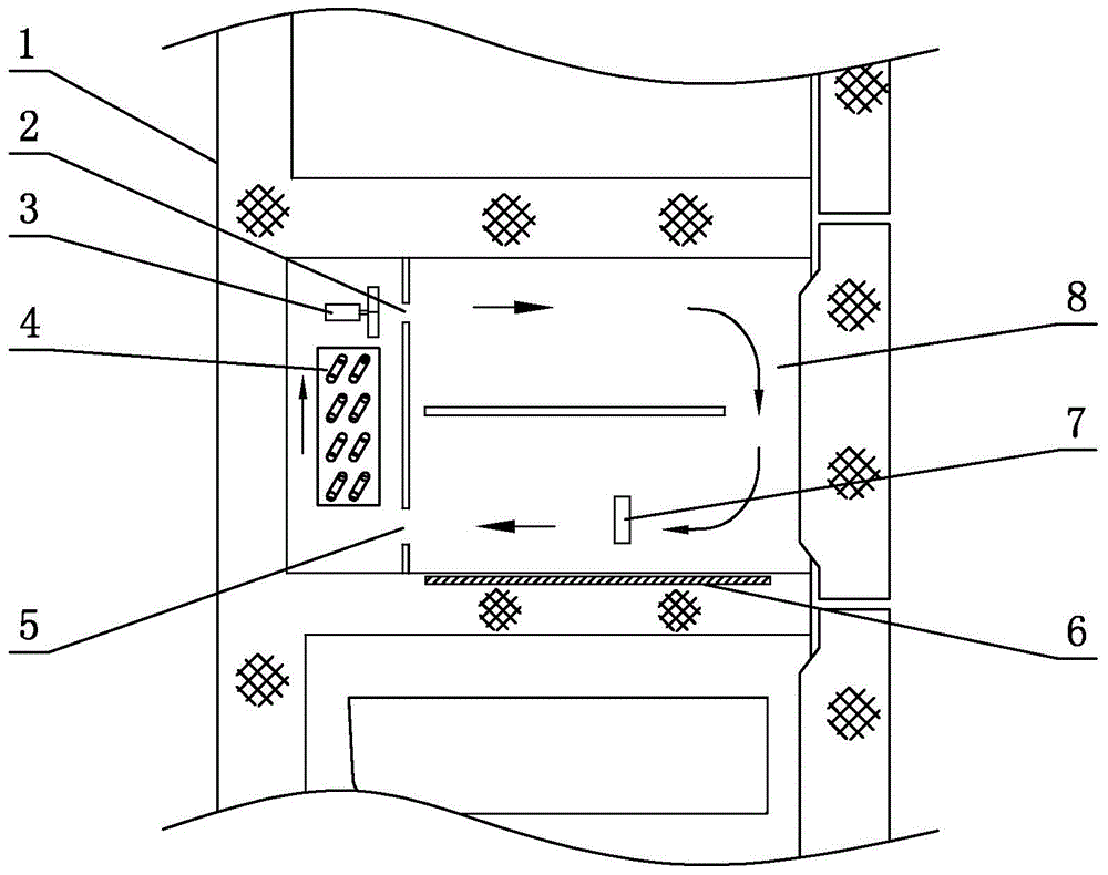
[0026] see figure 1 , the variable room of the refrigerator, including the variable room 8 arranged in the refrigerator and the circulating air duct arranged in the variable room 8, the circulating air channel is provided with a fan 3, an evaporator 4, a heating wire 6 and a temperature sensor 7; after the fan 3 starts , the air supply starts, and the air is sent to the variable room 8 through the air supply port 2, and then returns to the air return port 5 through the variable room 8 to realize the circulation of the internal air; the fan 3 and the evaporator 4 are arranged at the air supply port 2 and the return air port 5 In between, the moist air from the temperature-changing room 8 enters the evaporator 4, and the moisture in the air is condensed or frozen by the evaporator 4 to become dry air, which is then sent to the temperature-changing room 8 through the air outlet 2 to realize the Dehumidification control in variable room 8. In addition, the temperature sensor 7 de...

no. 2 example

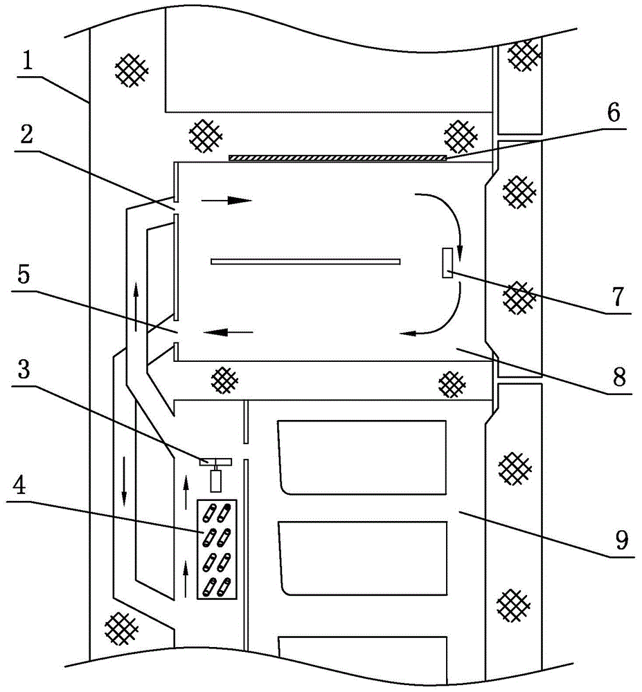
[0041] see image 3 , the variable room of this refrigerator is different from the first embodiment in that: the circulating air duct is not completely arranged in the variable room 8, and part of it is arranged on the lower freezing room 9. Therefore, the fan 3 and the evaporator 4 are all arranged on the Freezer 9 on. The temperature sensor 7 is arranged at different positions of the circulating air duct, in the middle of the variable room 8, and at the same time, the heating wire 6 can also be arranged at different positions of the circulating air channel, at the top of the variable room, this similar structure can also be used for The variable greenhouse implements dehumidification control to achieve the same effect.

[0042] Other parts not described are the same as those of the first embodiment, and will not be analyzed and described here.

no. 3 example

[0044] see Figure 4 , the variable room of this refrigerator is different from the first embodiment in that: the circulating air duct is not completely arranged in the variable room 8, and part of it is arranged on the upper freezing room 9, therefore, the fan 3 and the evaporator 4 are all arranged in the Freezer 9 on. The temperature sensor 7 is arranged on different positions of the circulating air duct, at the top of the variable chamber 8, and simultaneously, the heating wire 6 can also be arranged at different positions of the circulating air duct, at the middle of the variable chamber 8. This similar structure can also implement dehumidification control on the variable room to achieve the same effect.

[0045] Other parts not described are the same as those of the first embodiment, and will not be analyzed and described here.


PUM


Abstract

A refrigerator temperature varying chamber comprises a temperature varying chamber body arranged in a refrigerator. The refrigerator temperature varying chamber is characterized in that a circular duct is arranged inside or outside the temperature varying chamber body, and a fan, an evaporator, a heating wire and a temperature sensor are arranged on the circular duct at least. After the fan is turned on, air is pushed into the temperature varying chamber body by fan through an air supply opening and returns to a return air inlet via the temperature varying chamber body, damp air in the temperature varying chamber body enters the evaporator and is condensed or iced by the evaporator to become dry air, the dry air is then fed to the temperature varying chamber body through the air supply opening to complete circular delivery of the air, and meanwhile dehumidification controlling of the temperature varying chamber body is realized. The fan and the heating wire are controlled by a control element separately, the temperature sensor detects temperature and feeds back the temperature to the control element, the control element then controls the fan and the heating wire cooperatively according to a preset instruction, fluctuation of the room temperature within a reasonable range is ensured, and when the temperature is too low, the fan stops operation while the heating wire continues operation; when the temperature is too high, the heating wire stops operation and the fan fan continues operation.

Description

technical field [0001] The invention relates to a refrigerator temperature-changing room, in particular to a refrigerator temperature-changing room and a dehumidification control method thereof. Background technique [0002] At present, the common three-door air-cooled refrigerators on the market have refrigerators, freezers, and variable greenhouses. The temperature range of such variable greenhouses is generally -18 degrees to 5 degrees. Therefore, when the temperature control is adjusted from below zero to above zero, the water on the food will melt from ice to water, and the melted water will flow into the inside of the variable temperature chamber, where it is difficult to discharge. The more it accumulates, the user needs to clean it up to solve it, which brings a lot of trouble to the user's use. Contents of the invention [0003] The object of the present invention is to provide a refrigerator temperature-changing room with simple and reasonable structure, good de...

Claims


Application Information

Patent Timeline
Patent Type & Authority Applications(China)
IPC IPC(8): F25D29/00F25D21/04F25D11/02
CPCF25D11/02F25D21/04F25D29/005
Inventor 冯纬豪吴晓康
Owner GUANGDONG GALANZ GRP CO LTD
Learn More