
Constant pressure regulating valve

A technology of constant pressure valve and valve body, which is applied in the field of regulating constant pressure valves, and can solve problems such as waste of energy and waste of water resources

Inactive Publication Date: 2015-03-25
大连众瑞供热工程有限公司
View PDF8 Cites 6 Cited by
  • Summary
  • Abstract
  • Description
  • Claims
  • Application Information

AI Technical Summary

Problems solved by technology

[0002] At present, domestic high-end buildings such as hotels, clubs, guesthouses and other places often require 24-hour non-stop water supply in terms of hot water supply. Through the water supply pump, the hot water circulates between the pipeline and the water tank; if the hot water in the pipeline does not circulate , the heat will naturally dissipate out of the pipeline, and the user will discharge a large amount of low-temperature water when using it, wasting a lot of water resources
The commonly used method today is to circulate the hot water in the pipeline back to the water tank through the water supply pump, but when the number of users is small, it is still necessary to use the water supply pump for circulation, because the use of hot water requires a certain pressure. Used by the user side, resulting in a waste of energy

Method used


Image

  • Constant pressure regulating valve

Examples


Embodiment Construction

[0015] Embodiments of the present invention will be described in detail below in conjunction with the accompanying drawings.

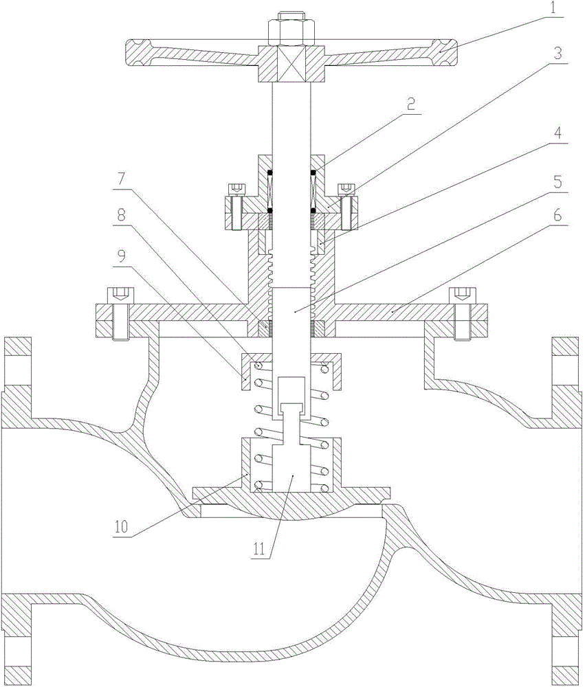
[0016] refer to figure 1 , the present invention provides an adjustable constant pressure valve, which includes a valve body, and a water inlet and a water outlet are opened at both ends of the valve body. A screw 5 with coaxial holes, the screw 5 includes a polishing rod part, a screw body and a lower polishing rod part sequentially connected from top to bottom, the polishing stem extends to the valve body, and a connecting part is provided at the end of the polishing rod part , a hand wheel 1 is fixed on the connecting part through a nut, and a mounting hole is opened on the side wall of the valve body, and an upper cover 6 is connected to the mounting hole through a flange, and a screw sleeve is formed on the upper cover 6, and the screw body passes through The trapezoidal thread fits in the screw sleeve, and the end of the screw sleeve is connecte...


PUM


Abstract

The invention provides a constant pressure regulating valve. The constant pressure regulating valve comprises a valve body, wherein a water inlet and a water outlet valve body which are communicated through a water hole are formed in the two ends of the valve body; a screw rod coaxial with the water hole is arranged on the valve body in sealed fit; the head part of the screw rod extends into the valve body; a spring sleeve is fixed on the part of the screw rod; a guide post is arranged on the end surface of the head part of the screw rod in sliding fit; a water baffling plate capable of covering the water hole and cutting off the water inlet and the water outlet is fixed on the end part of the guide post; a spring is arranged between the water baffling plate and the spring sleeve; the tail part of the screw rod extends out of the valve body; a hand wheel is fixed on the end part of the screw rod. The constant pressure regulating valve lifts the screw rod through clockwise rotation of the hand wheel, the spring fixing sleeve of the screw rod positions the pressure regulating spring so as to enable the water baffling plate to be in contact with the water hole of the valve body, and the rotation of the hand wheel stops when the pressure meets a requirement; the constant pressure regulating valve can also play a sealing role, and when the pressure of the pressure regulating spring is close to the maximum pressure, the bottom of the screw rod is in contact with the guide post and the water baffling plate completely seals the water hole so as to achieve a sealing aim.

Description

technical field [0001] The invention relates to a valve, in particular to a regulating constant pressure valve. Background technique [0002] At present, domestic high-end buildings such as hotels, clubs, guesthouses and other places often require 24-hour non-stop water supply in terms of hot water supply. Through the water supply pump, the hot water circulates between the pipeline and the water tank; if the hot water in the pipeline does not circulate , the heat will naturally dissipate out of the pipeline, and the user will discharge a large amount of low-temperature water when using it, wasting a lot of water resources. The commonly used method today is to circulate the hot water in the pipeline back to the water tank through the water supply pump, but when the number of users is small, it is still necessary to use the water supply pump for circulation, because the use of hot water requires a certain pressure. For the use of the user side, resulting in a waste of energy....

Claims


Application Information

Patent Timeline
IPC IPC(8): F16K17/30
CPCF16K17/30
Inventor 袁树权
Owner 大连众瑞供热工程有限公司
Learn More