Embedded leak-proof joint

A leak-proof and connecting piece technology, which is applied in waterway systems, indoor sanitary pipeline installations, drainage structures, etc., can solve the problems of joints without water seals, no secondary drainage, and poor water flow, so as to achieve convenient rotation and alignment , smooth water flow, good effect of anti-leakage effect

Inactive Publication Date: 2015-03-25
湖南中财化学建材有限公司
View PDF6 Cites 9 Cited by
  • Summary
  • Abstract
  • Description
  • Claims
  • Application Information

AI Technical Summary

Problems solved by technology

At present, in the construction process of civil construction, equipment installation, decoration construction, etc., the descending plate type drainage is secondary installation because holes are reserved first, and then pipes and fittings are installed in the second construction. The joints have no water seal and no secondary drainage function. , during the construction process, it is necessary to drill holes on the pipe fittings and install them. The method of backfilling and pouring concrete in the secondary construction is adopted. The operation is more cumbersome, and the installation is time-consuming and laborious, which reduces the installation efficiency; Due to aging and other reasons, water seepage occurs through the joints of the floor tiles and around the vertical pipe of the floor tiles. Generally, water-sealed leak-proof joints are used to deal with water seepage. Improper treatment will cause stinky puddles or leakage to the next floor due to water saturation. Or overflow to other rooms on the same floor, there are also non-water-sealed leak-proof joints, and the water flow has the problem of poor circulation; the installation between two adjacent floors is inconvenient due to the eccentricity of the pipe center

Method used


Image

  • Embedded leak-proof joint
  • Embedded leak-proof joint
  • Embedded leak-proof joint

Examples


Embodiment Construction

[0018] The present invention will be further described below by specific examples.

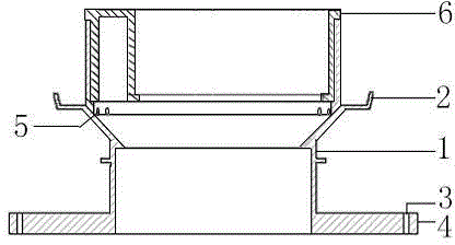
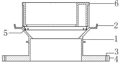
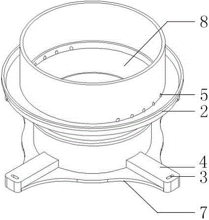
[0019] as attached figure 1 , attached figure 2 As shown, the pre-embedded leak-proof joint of the embodiment includes a leak-proof joint body 1, the upper end of the leak-proof joint body 1 is provided with a water guide groove 2, and a drain hole 5 is provided in the leak-proof joint body to realize the secondary drainage function. The lower end of the leak-proof joint body 1 is provided with a fixing ring, such as image 3 , Figure 5 As shown, the periphery of the fixed ring is provided with a plurality of chamfered round edges 7 and fixed feet 4, the chamfered rounded edges 7 and the fixed feet 4 alternate with each other, and the fixed feet 4 are provided with a fixed hole 3, and the fixed hole 3 is an elongated fixed hole , the length is 8mm-12mm, the width is 2mm-5mm, and the concentric circles are made into elongated holes at the fixed position, which is convenient for nailing. T...


PUM


Abstract

The invention discloses an embedded leak-proof joint used for the connecting position of pipelines for building decoration. The embedded leak-proof joint comprises a leak-proof joint body and a reducing connecting piece. A water guide groove is formed in the upper end of the leak-proof joint body, water drain holes are formed in the leak-proof joint body, a fixing ring is arranged at the lower end of the leak-proof joint body, the fixing ring is provided with fixing pins and fixing holes, the reducing connecting piece is connected with the leak-proof joint body, the eccentricity of the reducing connecting piece is -10 mm to +10 mm, anti-skid convex edges are arranged on the outer side of the reducing connecting piece, a plurality of lead angle type round edges are arranged on the periphery of the fixing ring, the lead angle type round edges and the fixing pins are spaced, the middle end of the leak-proof joint body is provided with a concave water drain ring and inward convex edges, the inward convex edges are connected with a pipeline, the horizontal distance between the outer side of each fixing hole and the outer side of a water guide groove is 2 mm to 5 mm, and the fixing holes are lengthened fixing holes. The embedded leak-proof joint has the advantages that embedded construction can be completed at a time, construction time is shortened, labor cost is reduced, installation is convenient, and installation efficiency is high.

Description

technical field [0001] The invention relates to a pipe connector for architectural decoration, in particular to a pre-embedded leak-proof joint. Background technique [0002] Same-layer drainage is more and more widely used in modern buildings, and it will become the trend of building drainage in the future. At present, in the construction process of civil construction, equipment installation, decoration construction and other constructions, the descending plate type drainage is secondary installation because holes are reserved before secondary construction and installation of pipes and fittings. The joints have no water seal and no secondary drainage function. , during the construction process, it is necessary to drill holes on the pipe fittings and install them. The method of backfilling and pouring concrete in the secondary construction is adopted. The operation is more cumbersome, and the installation is time-consuming and laborious, which reduces the installation effici...

Claims


Application Information

Patent Timeline
Patent Type & Authority Applications(China)
IPC IPC(8): E03F5/04E03C1/122
CPCE03C1/122
Inventor 徐永辉
Owner 湖南中财化学建材有限公司
Why Eureka
Try Eureka