Machining and conveying device for round tins

A technology for conveying devices and cans, which is applied in the directions of conveyor objects, transportation and packaging, and can solve the problems of high equipment cost and low efficiency of manual conveying methods.

Inactive Publication Date: 2015-03-25
重庆威萨特科技发展有限公司
View PDF0 Cites 1 Cited by
  • Summary
  • Abstract
  • Description
  • Claims
  • Application Information

AI Technical Summary

Problems solved by technology

[0003] The present invention mainly solves the problems of high equipment cost or low

Method used


Image

  • Machining and conveying device for round tins

Examples


Embodiment Construction

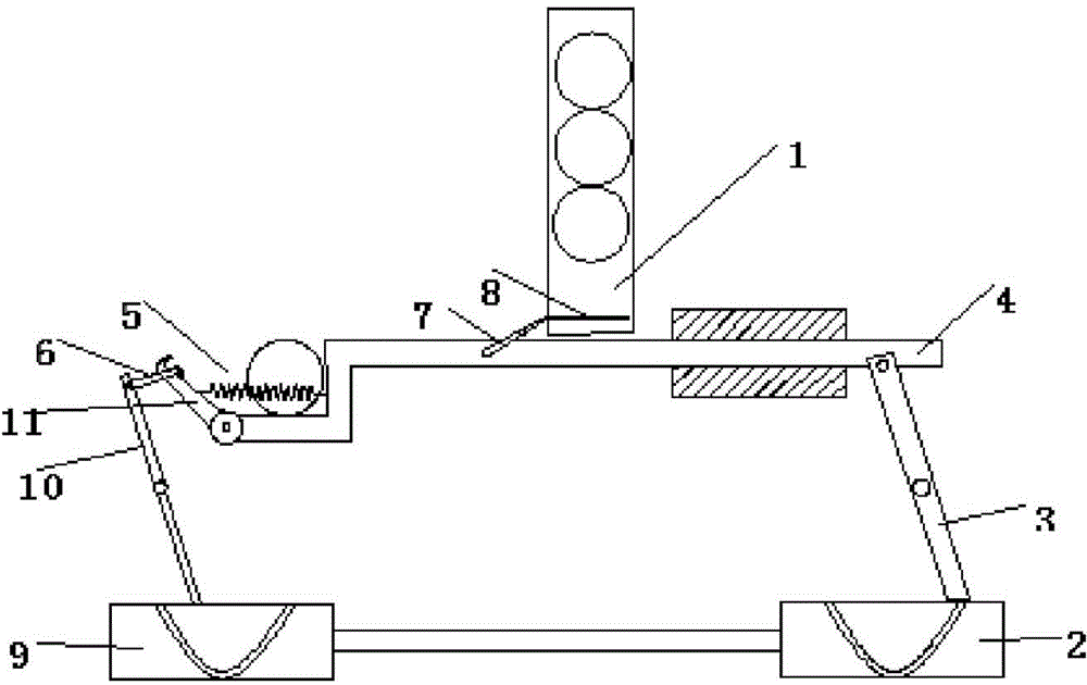
[0011] The reference signs in the description of the drawings are: storage cylinder 1 , first cam mechanism 2 , rotating arm 3 , conveying part 4 , accommodating groove 5 , swing plate 6 , linkage rod 7 , baffle plate 8 , second cam mechanism 9 , Rotating rod 10 , hooking member 11 .

[0012] like figure 1 As shown, this technical solution provides a processing and conveying device for round cans, including a frame, a conveying device, a storage cylinder 1, a separation device and a transition device. The storage cylinder 1 is vertically arranged on the frame and stores The side wall of the barrel 1 is provided with a through hole. The transmission device includes a first cam mechanism 2, a rotating arm 3, and a transmission part 4. The middle of the rotating arm 3 is hinged on the frame, and the two ends of the rotating arm 3 are respectively connected to the first cam mechanism. 2 and the conveying part 4, the conveying part 4 is provided with an accommodating groove 5 for ...


PUM


Abstract

The invention relates to a machining and conveying device for round tins. A storage barrel is vertically arranged on a rack, and through holes are formed in the side walls of the storage barrel. A conveying device body comprises a first cam mechanism, a rotary arm and a conveying part. The middle of the rotary arm is hinged to the rack, the two ends of the rotary arm are connected with the first cam mechanism and the conveying part respectively, a containing groove for containing one tin is formed in the conveying part, a swing plate capable of rotating around the bottom of the containing groove is arranged on the side wall of the containing groove, and the middle of the swing plate is connected to the conveying part through a tension spring. A separation part comprises a linkage rod and a baffle for isolating workpieces in the storage barrel, and the two ends of the linkage rod are hinged to the baffle and the conveying part respectively. A transition device comprises a second cam mechanism, a rotary rod and a hooking piece for hooking the swing plate, and the two ends of the rotary rod are connected to the second cam mechanism and the hooking piece respectively. By the adoption of the machining and conveying device, the problem that in the existing conveying technology for the round tins, equipment cost is high or manual efficiency is low is solved.

Description

technical field [0001] The invention is applied to the field of can conveying, and particularly relates to a processing conveying device for round cans. Background technique [0002] In the existing assembly line of mechanical production, manufacturing and processing, for the separation of large quantities of workpieces, the method of manipulator or manual separation is generally used, and some are completed by numerical control equipment, but such equipment is generally expensive and not applicable. in small workshops. For the manual separation processing method, a pile of workpieces are manually separated, and then the separated workpieces are placed one by one at the station to be processed for the next step. However, such a manual separation method is cumbersome, requires more personnel, is time-consuming and labor-intensive, and after all, human energy is limited, and long-term work will inevitably lead to poor spirits, resulting in an increase in the error rate of wor...

Claims


Application Information

Patent Timeline
IPC IPC(8): B65G47/06
Inventor 刘昌健
Owner 重庆威萨特科技发展有限公司
Why Eureka
Try Eureka