Dragon scooter type sliding robot with gravity adjusted based on inverted pendulum
An inverted pendulum and dragon driving technology, applied in the field of robotics, can solve the problems of increased weight of the robot's legs and unfavorable robot leg movement, etc., and achieve the effect of simple control, less control freedom, and strong fun
- Summary
- Abstract
- Description
- Claims
- Application Information
AI Technical Summary
Problems solved by technology
Method used
Image
Examples
Embodiment 1
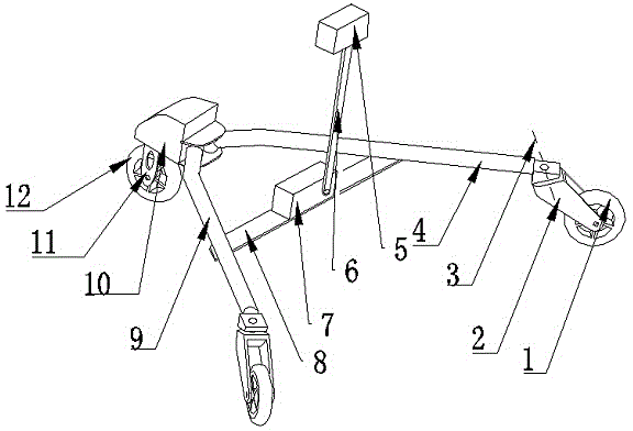
[0017] Such as figure 1 As shown, a dragon driving type sliding robot based on an inverted pendulum to adjust the center of gravity includes a rear wheel 1, a rear wheel frame 2, a tilting shaft 3, a right leg arm 4, a mass block 5, a swing rod 6, an inverted pendulum control device 7, Fixed plate 8, left leg arm 9, platform 10, front wheel frame 11, front wheel 12; Described rear wheel 1 is installed on the rear wheel frame 2, and described rear wheel frame 2 and right leg arm 4 and left leg arm 9 The wedge block at the end is connected, and there is a certain angle between the inclined shaft 3 that the rear wheel frame 2 rotates around the two leg arms and the vertical line on the ground; the other end of the right leg arm 4 is fixedly connected with the platform 10, and the left The leg arm 9 and the right leg arm 4 are symmetrically installed on the platform 10, and the two leg arms are fixedly connected by a fixed plate 8; the inverted pendulum control device 7 is install...
Embodiment 2
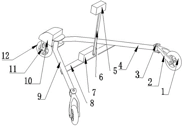
[0019] Such as figure 2 As shown, this embodiment is basically the same as Embodiment 1, the difference is that the end connection of the right leg arm 4 and the left leg arm 9 adopts a U-shaped structure, and the rear wheel frame 2 is connected and installed on the U-shaped structure. Make the joint form a rotating pair; the upper and lower holes of the U-shaped structure are equal in size, and there is a certain angle between the connection line of the centers of the two holes and the vertical line of the ground, so the rotation axis of the rear wheel frame 2 and the vertical line of the ground There is a certain angle between the lines.
Embodiment 3
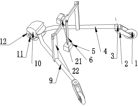
[0021] Such as image 3 As shown, this embodiment is basically the same as Embodiment 1, the difference is that a gantry 22 is fixedly installed between the right leg arm 4 and the left leg arm 9, and the pendulum control box 21 is installed on the gantry 22 At the center of the crossbeam, one end of the pendulum 6 is installed on the pendulum control box 21 , and the other end is fixedly connected with the mass block 5 .
PUM
 Abstract
Description
Claims
Application Information
 - R&D
- Intellectual Property
- Life Sciences
- Materials
- Tech Scout
- Unparalleled Data Quality
- Higher Quality Content
- 60% Fewer Hallucinations
Browse by: Latest US Patents, China's latest patents, Technical Efficacy Thesaurus, Application Domain, Technology Topic, Popular Technical Reports.
© 2025 PatSnap. All rights reserved.Legal|Privacy policy|Modern Slavery Act Transparency Statement|Sitemap|About US| Contact US: help@patsnap.com


