
Vehicle-mounted cooling air duct system ventilated via negative pressure

A technology of air circulation and negative pressure, which is applied in air handling equipment, vehicle parts, and road transportation emission reduction, etc. The effect of less and lower cost

Inactive Publication Date: 2015-03-25
厦门锐思达机电科技有限公司
View PDF9 Cites 4 Cited by
  • Summary
  • Abstract
  • Description
  • Claims
  • Application Information

AI Technical Summary

Problems solved by technology

The solar panels used in this method are expensive, the power consumption of semiconductor refrigerators is large, and the laying of solar panels outside the car affects the overall aesthetics of the car
Another example is that the patent No. ZL 02241251.4 proposes a "water evaporative refrigeration air conditioner" for vehicles. This patent utilizes the air that is passed into the passage during the driving process of the car to carry out water evaporation and cooling treatment and then pass it into the compartment. The air passing into the compartment contains damp water vapor, which affects the normal operation of instruments and meters in the vehicle and is not conducive to people's health
Also, the existing indirect evaporative air conditioners require at least two or more fans for ventilation and cooling, increasing the cost of accessories

Method used


Image

  • Vehicle-mounted cooling air duct system ventilated via negative pressure
  • Vehicle-mounted cooling air duct system ventilated via negative pressure
  • Vehicle-mounted cooling air duct system ventilated via negative pressure

Examples


Embodiment Construction

[0018] In order to make the above objects, features and advantages of the present invention more comprehensible, the present invention will be further described in detail below in conjunction with the accompanying drawings and specific embodiments.

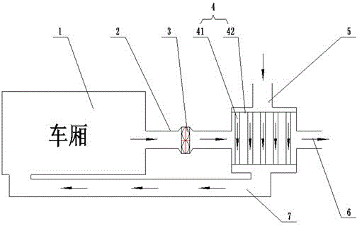
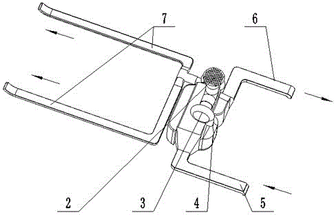
[0019] Such as figure 1 with figure 2 . A vehicle-mounted cooling air duct system using negative pressure for air circulation, which consists of a compartment conduction heat exchanger 4, an exhaust fan 3, a secondary air duct 2, a moist air duct 6, a primary air duct 5, a dry and cold air duct 7 and Compartment 1 is composed.

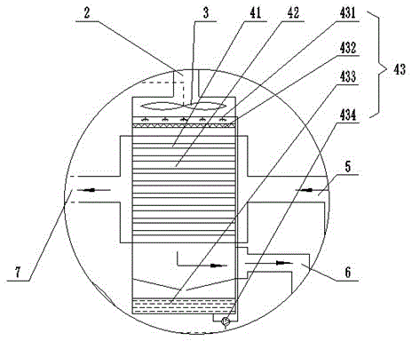
[0020] Such as image 3 , is a schematic diagram of an embodiment of a compartment conduction heat exchanger. The compartment conduction heat exchanger 4 includes an evaporation chamber 42, a heat conduction chamber 41 and a water pump circulation unit 43; the evaporation chamber 42 is located in the outer space of several pipelines, and the evaporation chamber 42 uses the principle of water evaporati...


PUM


Abstract

The invention provides a vehicle-mounted cooling air duct system ventilated via negative pressure. The system comprises a separate-cavity-conduction type heat exchanger, an exhaust fan, a secondary air conduit, a moist air conduit, a primary air conduit, a dry cold air conduit and a carriage. The secondary air conduit, the exhaust fan, the cavity of the separate-cavity-conduction type heat exchanger and the moist air conduit are connected sequentially, air in the carriage is extracted by the exhaust fan and transmitted to the separate-cavity-conduction type heat exchanger to evaporate, moist cold air generated is discharged through the moist air conduit, and negative pressure is generated in the carriage. The primary air conduit, the heat conducting cavity of the separate-cavity-conduction type heat exchanger and the dry cold air conduit are connected sequentially, air under the bottom of the vehicle is absorbed by the primary air conduit inlet and transmitted to the separate-cavity-conduction type heat exchanger to generate dry cold air, and the dry cold air is transmitted to the front of the carriage through the dry cold air conduit. Thereby, the vehicle-mounted cooling air duct system adopting negative pressure to proceed ventilation has the advantages of being free of pollution, healthy and friendly to environment, low in construction cost, less in energy consumption and no effect to overall appearance of vehicles.

Description

technical field [0001] The invention relates to the field of automobile ventilation, in particular to a vehicle-mounted cooling air duct system that uses the principle of negative pressure to ventilate automobiles. Background technique [0002] With the rapid development of science and technology, all kinds of cars are being introduced, but the good ventilation of cars has always been one of the hot spots that people pay attention to. Most existing cars use compressors for refrigeration and ventilation, and compressors use freon that pollutes the atmosphere, which will damage the environment; some cars use solar energy for cooling and ventilation, such as the patent No. ZL 01262232. A "solar cooling device for cars", this patent uses solar cells laid on the top of the car and the rear cover box to supply power to the refrigeration device including the semiconductor cooler, and the air temperature is lowered and then passed into the compartment to achieve cooling and ventilat...

Claims


Application Information

Patent Timeline
Patent Type & Authority Applications(China)
IPC IPC(8): B60H1/32
CPCY02T10/88B60H1/0025B60H1/00321
Inventor 黄种明程龙杨星张智勇李坤煌
Owner 厦门锐思达机电科技有限公司
Learn More