Pressable Hole Stapler

A stapler and hole needle technology, which is applied in staple tools, metal processing, nailing tools, etc., can solve the problems of inability to bind, staples cannot be bent, complex structure, etc., and achieve simple and reasonable structure, secure The effect of reliability and structural integrity

Inactive Publication Date: 2016-02-24
CHENGDU UNIVERSITY OF TECHNOLOGY
View PDF9 Cites 0 Cited by
  • Summary
  • Abstract
  • Description
  • Claims
  • Application Information

AI Technical Summary

Problems solved by technology

In order to solve this problem, some designs have appeared, such as the Chinese patent, the integrated stapler for pressing holes and binding with the publication number of 2794838. The functions of pressing holes and binding are realized by adjusting the positions of the transposition mechanism, but the structure for realizing its functions is complicated.
Chinese patent, publication number is a kind of stapler of 201143803, realizes the pressing hole function by the stapler that is installed on the pressing handle, the advantage is that the structure is simple, but the stapler of this design overlaps with the outlet hole of the staple, and the function Interfering with the structure, it is difficult to implement. In addition, the design only has a pair of staple holes on the base, and the bending groove is canceled, so that the staples cannot be bent and cannot be bound during binding.

Method used


Image

  • Pressable Hole Stapler
  • Pressable Hole Stapler
  • Pressable Hole Stapler

Examples


Embodiment Construction

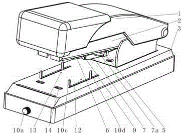
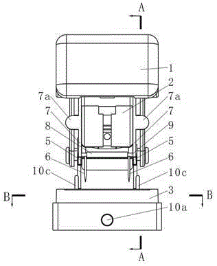
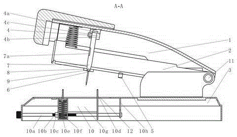
[0030] like figure 1 , figure 2 , image 3 , Figure 4 , Figure 5 , Image 6 , Figure 7 As shown, the pressing handle 1 and the needle storage box 2 are hinged on the base 3 through the base pin 11 . The shaft hole plate 8 is an elongated plate with a through hole in the length direction, the hole axis is perpendicular to the side wall of the needle storage box 2, and is connected to the bottom surface of the needle storage box 2 near the front end. The rotating shaft 9 passes through the through hole of the shaft hole plate 8 . There are two pressing pins 6, and the spacing between the two pressing pins 6 is the same as the spacing between the two pins of the staple, and they are connected in parallel on the rotating shaft 9 protruding from the shaft orifice plate 8 both sides. There are two struts 7, which are rod-shaped parts, and are connected with breaking ears 7a, which are respectively connected to the two ends of the rotating shaft 9. The connected struts 7 a...


PUM


Abstract

The invention discloses a stapler capable of punching. A shaft hole plate is a long plate with a hole; a rotating shaft passes through the through hole of the shaft hole plate; two punching pins are connected with the rotating shaft; a brace rod is connected with two ends of the rotating shaft; a lower positioning piece is arranged on the side surface of a pin storage box; an upper positioning piece is fixedly arranged on the inner side of the top surface of a pressing handle; the upper plate of a base is provided with two parallel slots and is further provided with two pin penetrating holes; a spring box is arranged in the base and is contacted with the upper plate of the base; an adjusting nut is connected with the spring box; a spring is arranged in the spring box and is used for enabling the heads of a movable retaining fork to extend out of the slots of the base; a fixed retaining fork is arranged at the rear part of the spring box and is connected with the spring box through a connection plate; the distance between the movable retaining fork and a bending slot is equal to that between the fixed retaining fork and the pin penetrating holes; a support plate is arranged at the rear part of the fixed retaining fork; one end of the adjusting rod is provided with an adjusting knob, and the other end of the adjusting rod is provided with a ring-like clamping slot, wherein the ring-like clamping slot is matched with the through hole of the support plate; and a middle outer thread of the adjusting rod is matched with the adjusting nut. The stapler capable of punching is simple in structure, is reliable in function and is capable of positioning the stapling margin.

Description

technical field [0001] The invention relates to stationery, in particular to a stapler capable of pressing holes. Background technique [0002] Ordinary staples need to be bent during the binding process, so hard materials cannot be used. When binding some thicker and harder paper, the stapler will be bent or jammed due to insufficient hardness of the staples, resulting in Could not staple. At this time, it is very troublesome to first press the holes with the help of a separate hole press and then bind them. In order to solve this problem, some designs have appeared, such as the Chinese patent, the integrated stapler for pressing holes and binding with the publication number of 2794838. The functions of pressing holes and binding are realized by adjusting the positions of the transposition mechanism, but the structure for realizing its functions is complicated. . Chinese patent, publication number is a kind of stapler of 201143803, realizes the pressing hole function by ...

Claims


Application Information

Patent Timeline
Patent Type & Authority Patents(China)
IPC IPC(8): B25C5/00B25C7/00B26F1/24
CPCB25C5/00B25C7/00B26F1/24
Inventor 杨勇李堰炜赵志安
Owner CHENGDU UNIVERSITY OF TECHNOLOGY
Why Eureka
Try Eureka