
Oscillating type pneumatic clamping reverse force arm mechanism

A pneumatic clamping and reaction arm technology, applied in metal processing, metal processing equipment, manufacturing tools, etc., can solve problems such as inability to achieve fast and accurate positioning operations, delay in production efficiency, troubles, etc.

Active Publication Date: 2015-03-25
DALIAN HAOSEN EQUIP MFG
View PDF12 Cites 0 Cited by
  • Summary
  • Abstract
  • Description
  • Claims
  • Application Information

AI Technical Summary

Problems solved by technology

The problem with this method is that it is troublesome for the operator to move the reaction arm mechanism and position it accurately with the bolt, and it is impossible to achieve fast and accurate positioning operation, which delays the production efficiency
Moreover, during the tightening process, the operator needs to hold the reaction arm mechanism to bear a part of the reaction arm, which sometimes cannot be achieved only by the strength of the operator.

Method used


Image

  • Oscillating type pneumatic clamping reverse force arm mechanism
  • Oscillating type pneumatic clamping reverse force arm mechanism
  • Oscillating type pneumatic clamping reverse force arm mechanism

Examples


Embodiment Construction

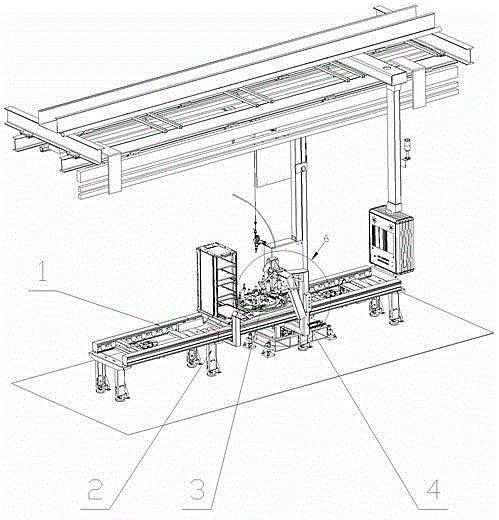
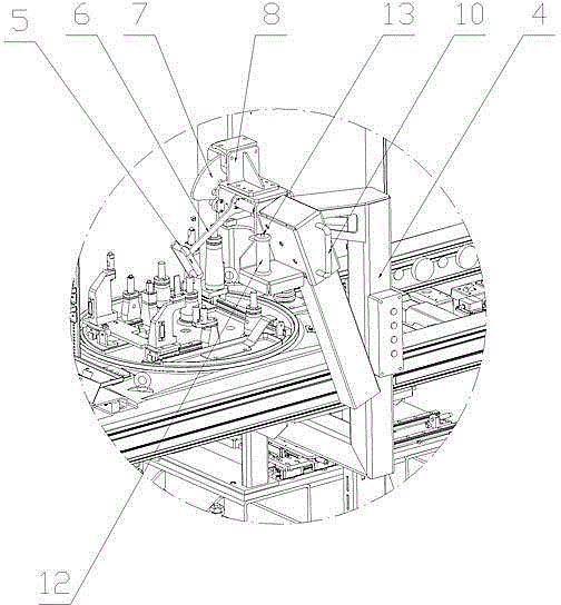
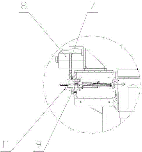
[0010] The specific implementation manner of the present invention will be described below with reference to the accompanying drawings. Such as figure 1 , figure 2 , image 3 Shown: a swing-type pneumatic clamping reaction arm mechanism, including a frame 2 fixed on the foundation ground, a roller table 1 is arranged on the frame 2, and a pallet 3 for transporting workpieces is provided matching the roller table 1 , a support frame 4 is fixedly arranged on the frame 2, and a swingable swing rod 6 is rotatably supported on the support frame 4. The end of the swing rod 6 is provided with a swing handle 5. When the swing rod 6 rotates, it can also drive a fan-shaped The disc 7 and the counter force arm tightening mechanism 9 rotate, and the fan-shaped disc 7 is provided with an air lock device 8, while the counter force arm tightening mechanism 9 is supported on the support frame 4 in an axially movable manner (the sector disc 7 and The reaction arm tightening mechanism 9 can...


PUM


Abstract

The invention discloses an oscillating type pneumatic clamping reverse force arm mechanism. The oscillating type pneumatic clamping reverse force arm mechanism comprises a rack (2) provided with a roller bed (1), and a tray (3) for conveying workpieces is arranged on the roller bed (1). The oscillating type pneumatic clamping reverse force arm mechanism is characterized in that a supporting frame (4) is arranged on the rack (2), an oscillating bar (6) with an oscillating handle (5) is rotationally supported by the supporting frame (4), the oscillating bar (6) can drive a sector-shaped disk (7) to rotate, an air locking device (8) matched with the sector-shaped disk (7) is arranged, a reverse force arm screwing mechanism (9) which is arranged on the supporting frame (4) and can axially float can rotate along with the oscillating bar (6) at the same time, a pushing handle (10) is arranged at the tail end of the reverse force arm screwing mechanism (9), at least two positioning shafts (11) are arranged at the front end of the reverse force arm screwing mechanism (9), a working handle (12) is arranged on the supporting frame (4), and a button (13) capable of controlling the work of the reverse force arm screwing mechanism (9) is arranged at the top end of the working handle (12).

Description

technical field [0001] The invention relates to a reaction arm tightening mechanism, in particular to a swing type pneumatic clamping reaction arm mechanism. Background technique [0002] When installing some workpieces, it is necessary to use the reaction arm mechanism to tighten the bolts on the workpiece to realize the connection between the workpieces. The traditional reaction arm mechanism requires the operator to hold the handle on it to move, so that the reaction The tightening mechanism on the moment arm mechanism moves to the bolt of the workpiece for tightening operation. The problem with this method is that it is cumbersome for the operator to move the reaction arm mechanism and position it accurately with the bolt, and it is impossible to achieve fast and accurate positioning operation, which delays the production efficiency. And in the tightening process, it is necessary for the operator to hold the reaction arm mechanism to bear a part of the reaction arm, whi...

Claims


Application Information

Patent Timeline
IPC IPC(8): B23P19/06
CPCB23P19/06
Inventor 刘云飞杨宁宋万国赵方灏
Owner DALIAN HAOSEN EQUIP MFG
Learn More