Milling cutter

A milling cutter and cutter body technology, applied in the direction of milling cutters, milling machine equipment, manufacturing tools, etc., can solve the problems of complex operation, low processing efficiency, and low milling precision, and achieve convenient operation, simple structure, improved milling efficiency and milling The effect of precision

Inactive Publication Date: 2015-03-25
赵立平
View PDF0 Cites 2 Cited by
  • Summary
  • Abstract
  • Description
  • Claims
  • Application Information

AI Technical Summary

Problems solved by technology

In the actual milling process, the blade is usually not movable on the cutter body, and can only mill the workpiece within a fixed range, and the position of the workpiece needs to be adjusted continuously, and the milling will be repeated at some positions on the workpiece, resulting in complicated operations. The processing efficiency is low, and the milling accuracy is not high

Method used


Image

  • Milling cutter
  • Milling cutter

Examples


Embodiment Construction

[0016] The technical solutions in the embodiments of the present invention will be clearly and completely described below in conjunction with the accompanying drawings. Apparently, the described embodiments are only some, not all, embodiments of the present invention. Based on the embodiments of the present invention, all other embodiments obtained by persons of ordinary skill in the art without making creative efforts belong to the protection scope of the present invention.

[0017] The invention discloses a milling cutter, which is used on a milling machine for milling, so as to achieve the purpose of improving work efficiency and milling precision.

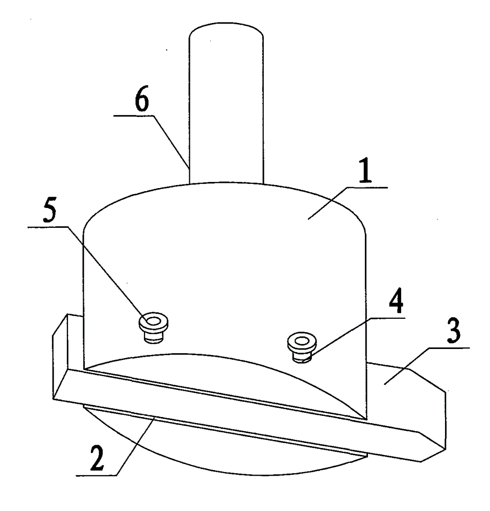
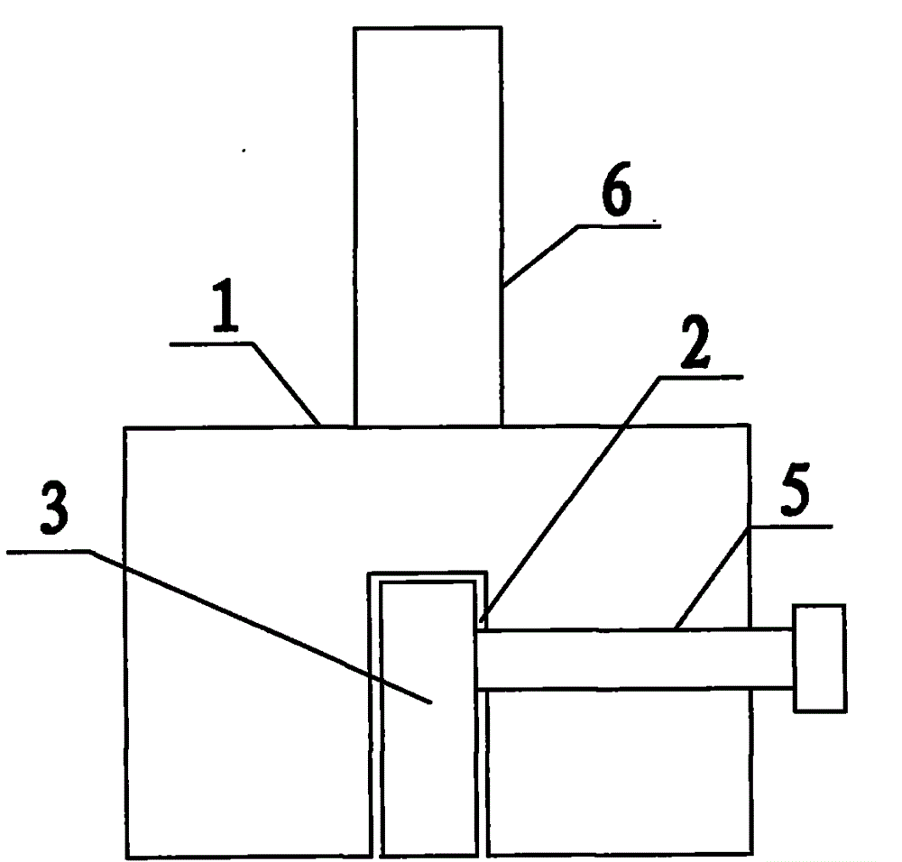
[0018] Such as figure 1 with figure 2 As shown, the present invention is made up of cutter body 1 and fixed end 6, and blade 3 is embedded in the groove 2 that cutter body 1 bottom opens, and is fixed by the bolt 5 in the screw hole 4.

[0019] refer to figure 1 with figure 2 , when the present invention is used for imple...


PUM


Abstract

The invention discloses a milling cutter which comprises a fixed end and a cutter body, the fixed end is arranged on the cutter body, a groove is arranged at the bottom of the cutter body, screw holes are arranged on the lateral side, bolts are arranged in the screw holes which are communicated with the groove, and a cutter bade is movably embedded in the groove. When the milling cutter is used for milling, the position of the cutter blade in the groove can be adjusted according to actual needs, the milling range is changed, the structure is simple, the operation is simple, and the processing efficiency and the milling accuracy can be well improved.

Description

technical field [0001] The invention relates to a milling cutter for milling operations. Background technique [0002] Milling cutters are mainly used for milling on milling machines. According to different processing needs, the requirements for milling cutters are also different. As the most important part of the milling cutter, the insert is usually integrated with the cutter body or brazed on the cutter body, which causes the milling range to be affected by the shape of the cutter body and the position of the insert. In the actual milling process, the blade is usually not movable on the cutter body, and can only mill the workpiece within a fixed range, and the position of the workpiece needs to be adjusted continuously, and the milling will be repeated at some positions on the workpiece, resulting in complicated operations. The processing efficiency is low, and the milling accuracy is not high. Contents of the invention [0003] In order to solve the above technical p...

Claims


Application Information

Patent Timeline
IPC IPC(8): B23C5/20B23C5/22
CPCB23C5/2208B23C2210/168B23C2210/24
Inventor 赵立平
Owner 赵立平
Why Eureka
Try Eureka