
Novel dross removal device

A new type of slag removal technology, applied in the direction of charge control, lighting and heating equipment, furnace components, etc., can solve the problems of affecting the quality of casting damage, short service life of slag removal plates, and prolonging slag removal time, so as to reduce operating failures and The consumption of slag scraping plate, prolonging the service life and improving the effect of slag scraping efficiency

Inactive Publication Date: 2015-03-25
天津吉泰空调通风设备有限公司
View PDF0 Cites 2 Cited by
  • Summary
  • Abstract
  • Description
  • Claims
  • Application Information

AI Technical Summary

Problems solved by technology

During the slag removal process, it is required that the lifting action of the slag removal plate should be the closest to the tank wall without scraping the tank wall. However, in the actual operation process, this requirement cannot be met at all due to the inability to observe closely, which results in poor efficiency of slag removal. Low, directly prolonging the slag removal time
At the same time, most of the slag removal plates currently used are fixed installation methods, which are heavy, inconvenient to disassemble and assemble, and the rigid connection wears a lot, and the service life of the slag removal board is short; the slag removal effect varies from person to person, resulting in molten iron, molten steel The loss and its temperature drop are relatively large
[0003] Moreover, the existing ladle (or ladle) slag removal process is relatively simple, relying only on manual visual inspection of the steel slag level and manual operation of the slag removal machine to carry out slag removal. The labor intensity of medium operators is relatively high

Method used


Image

  • Novel dross removal device

Examples


Embodiment Construction

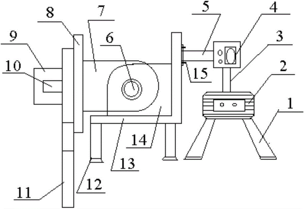
[0015] Attached below figure 1 The present invention will be further described with reference to specific embodiments.

[0016] The present invention provides a new type of slag removal device, which is characterized in that it includes a motor 2, a numerical control instrument 4, an "L"-shaped support 13 and a slag removal plate 11, and the motor 2 is connected to the numerical control instrument 4 The rod 3 is connected, the numerical control instrument 4 is connected with the "L"-shaped support 13 through the telescopic arm 5, which realizes the automation of the slag removal process, improves the slag removal efficiency, and reduces the labor intensity of the operator. The arm 5 and the "L"-shaped support 13 are fixed by a nut 15, and the "L"-shaped support 13 is welded with a single ear plate 14, and the single ear plate 14 is movable with the double ear plate through the hinge shaft 6 7, the double ear plate 7 is welded on the inner side of the stop plate 8, the outer s...


PUM


Abstract

The invention provides a novel dross removal device. The novel dross removal device comprises a motor, a numerical control instrument, an L-shaped support and a dross removal plate. The motor is connected with the numerical control instrument through a connecting rod, the numerical control instrument is connected with the L-shaped support through a stretchable arm, the stretchable arm is fixed to the L-shaped support through nuts, a single-lug plate is welded to the interior of the L-shaped support and movably connected with a double-lug plate through a hinged shaft, the double-lug plate is welded to the inner side of a stop plate, a hanging rod is arranged on the outer side of the stop plate, the dross removal plate with a hanging rod hole is fixed to the hanging rod through a locking pin, and a plate head of the dross removal plate is in an circular arc shape. The novel dross removal device is simple in design and convenient to use; as the numerical control instrument is installed, automation of the dross removal process is achieved, the dross removal efficiency is improved, and the labor intensity of an operator is reduced. The novel dross removal device is suitable for dross removal of steel ladles and hot metal ladles and also suitable for dross removal of various other furnaces.

Description

technical field [0001] The invention belongs to the field of metallurgical machinery, and in particular relates to a slag removing device for removing slag from molten iron and molten steel before billet casting. Background technique [0002] In production, it is necessary to remove the slag before casting to avoid resulfurization and rephosphorization of molten iron and molten steel, making it more pure, so as to obtain high-quality casting slabs. Existing slag removal equipment uses a slag removal board to remove slag, and the slag removal board is fixed on the telescopic arm of the slag removal machine, and moves with the telescopic arm in six directions: front and rear, left and right, and up and down. During the slag removal process, it is required that the lifting action of the slag removal plate should be the closest to the tank wall without scraping the tank wall. However, in the actual operation process, this requirement cannot be met at all due to the inability to ...

Claims


Application Information

Patent Timeline
Patent Type & Authority Applications(China)
IPC IPC(8): B22D43/00F27D3/15
CPCB22D43/007F27D3/1563
Inventor 赵富娥
Owner 天津吉泰空调通风设备有限公司
Learn More