
Graphics processing systems

A graphics processing and graphics technology, applied in the field of graphics processing systems based on tiles, to achieve the effect of improving system performance and reducing power consumption

Active Publication Date: 2015-03-18
ARM LTD
View PDF6 Cites 19 Cited by
  • Summary
  • Abstract
  • Description
  • Claims
  • Application Information

AI Technical Summary

Problems solved by technology

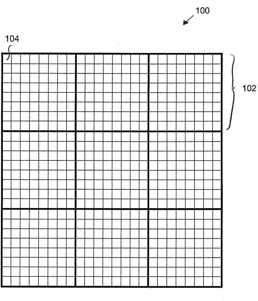
[0020] In graphics processors in low-power and portable devices, the bandwidth cost of writing data from the graphics processing pipeline to external memory and the feedback for reading data from external memory to the local memory of the graphics processing pipeline for deferred shading Bandwidth cost to operate can be a significant issue

Method used


Image

  • Graphics processing systems
  • Graphics processing systems
  • Graphics processing systems

Examples


Embodiment Construction

[0210] In the figures, the same reference numerals are used for the same features, where appropriate.

[0211] Preferred embodiments of the invention will now be described in the context of the processing of computer graphics for display.

[0212] As is known in the art and as discussed above, when a computer graphics image is to be displayed, the image is typically first defined as a series of primitives (polygons) which are then divided (rasterized) into Graphics fragment for graphics rendering. During normal graphics rendering operations, the renderer will modify (for example) color (red, green and blue, RGB) and transparency (alpha, α) data associated with each fragment so that the fragments can be displayed correctly. After fragments have fully traversed the renderer, their associated data values ​​are stored in memory, ready to be output for display.

[0213] The present invention relates to a tile-based graphics processing pipeline, i.e. wherein the graphics processin...


PUM


Abstract

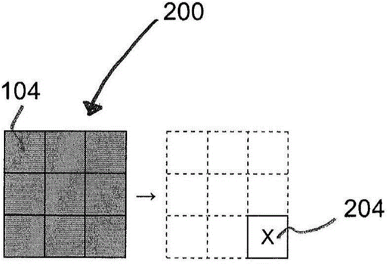
When processing a set of tiles to generate an output in a tile based graphics processing pipeline, the pipeline, for one or more tiles of the set of tiles, renders one or more render targets containing data to be used in a processing operation (602), and stores the render targets in the tile buffer (604). It also stores some but not all of the sampling position values for a render target or targets for use when processing an adjacent tile of the set of tiles (606). It then performs a processing operation for the tile using the stored render target or targets (608) and one or more stored sampling position values from another, adjacent tile of the set of tiles (610), to generate an output for the tile (612).

Description

technical field [0001] The present invention relates to graphics processing systems, and in particular to tile-based graphics processing systems. Background technique [0002] As is known in the art, it is common to enable easier Perform graphics processing operations. These "primitives" are usually in the form of simple polygons, such as triangles. [0003] Graphics primitives are typically generated by the graphics processing system's application programming interface using graphics drawing instructions (requests) received from applications requiring graphics output (eg, games). [0004] Each primitive at this stage is usually defined and represented by a set of vertices. Each vertex of a primitive is associated with a set of data representing that vertex, such as position, color, texture, and other attribute data. This data is then used, for example, when rasterizing and rendering the vertex (the primitive(s) to which the vertex relates) in order to generate the desir...

Claims


Application Information

Patent Timeline
IPC IPC(8): G06T1/00
CPCG06T1/20G06T11/40G06T15/005G06T11/001
Inventor S·T·埃利斯J·尼斯塔德A·恩格-哈斯特维德
Owner ARM LTD
Learn More