


Quick Research
Generate reliable direction feasibility study reports for your R&D in just a few steps.

Technical Q&A
Discover and master advanced knowledge NOW. Basics, ideas, possibilities, all at once.

Find Solutions
As an expert in R&D theories, this can generate solutions to your technical problems instantly.

Evaluate Feasibility
Analyze your overall solution with one click, know your potential R&D risks in advance.

Monitor Landscape
Get weekly tech updates, stay abreast of the latest tech innovations and key insights.
Lamp device
A technology for lamps and components, which is applied in the field of lamps that are easy to maintain, can solve the problems of inconvenient product maintenance, inconvenient maintenance of permanent installation, and large installation and maintenance needs, and achieves the effect of saving time and effort in the process of opening the cover.
- Summary
- Abstract
- Description
- Claims
- Application Information
AI Technical Summary
Problems solved by technology
Method used
Image

Examples
Embodiment 1
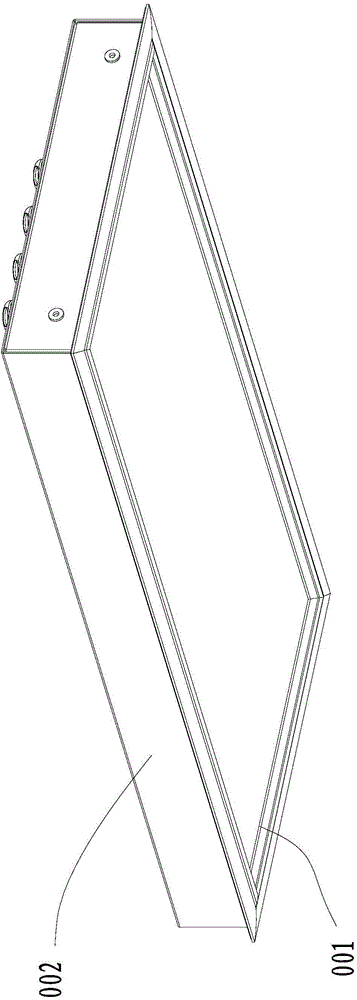
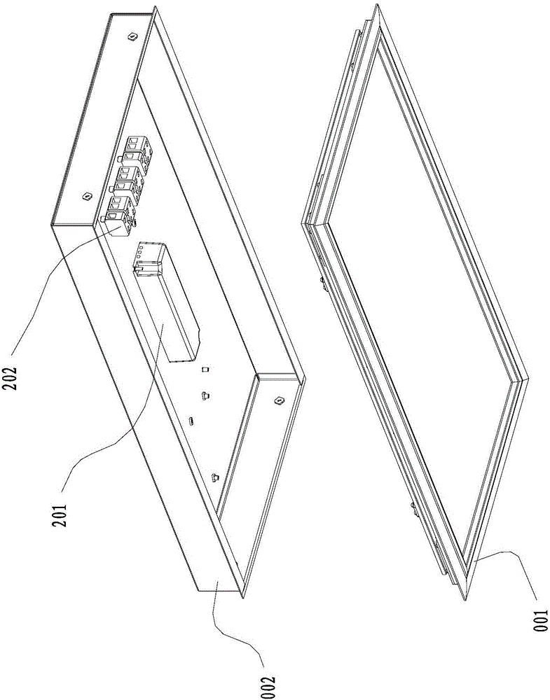
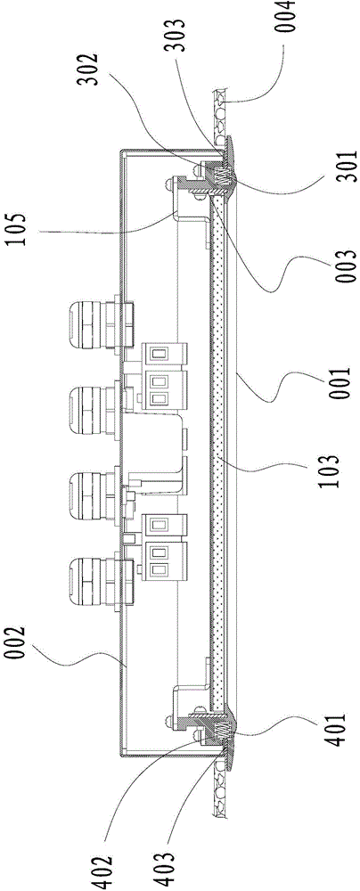
[0028] Such as Figure 1 ~ Figure 3 As shown, the embodiment of the present invention provides a lamp, which can be used as an embedded LED panel lamp or the like. The lamp above includes a front frame assembly 001 and a rear shell assembly 002 , the front frame assembly 001 is connected to the rear shell assembly 002 , and the rear shell assembly 002 can be embedded and fixedly installed in the ceiling 004 . A light source assembly 003 is connected to the front frame assembly 001 or the rear shell assembly 002 . The opposite sides of the front frame assembly 001 are provided with a first card slot 402 and a second card slot 302. In this embodiment, the first card slot 402 is provided on the left side of the front frame assembly 001, and the second card slot 302 is provided On the right side of the front frame assembly 001. It can be understood that the orientation terms such as left and right in this embodiment are only relative concepts or refer to the normal use state of ...
Embodiment 2
[0045] Different from the positions of the first card slot, the second card slot, the first card edge, and the second card edge in Embodiment 1, in this embodiment, the opposite sides of the front frame assembly are provided with the first card edge and the second card edge. The second card edge, the rear shell assembly has a first card slot and a second card slot facing oppositely, the first card edge extends into the first card slot, the second card edge extends into the second card slot, and the first card slot A first elastic piece is arranged inside, one end of the first elastic piece is against the first card slot, and the other end is against the first card edge; a second elastic piece is arranged inside the second card slot, and one end of the second elastic piece is against the first card slot The other end of the second card slot is against the second card edge.
Embodiment 3
[0047] Specifically, in this embodiment, on the basis of the first and second embodiments, an improvement on the reflective film cover is added. Such as Figure 8 shown, and refer to Figure 4 , the rear shell assembly 002 is provided with a wire passing hole, a plurality of wire passing holes can be provided, and a wire passing protective sleeve 203 can be set on the edge of the wire passing hole. The front frame assembly 001 is provided with a reflective film and a reflective film cover 112 , and the light guide plate assembly 103 , the reflective film, and the reflective film cover 112 are sequentially stacked inside the front frame assembly 001 . One side of the reflective film cover plate 112 is pressed against the reflective film, and the other side of the reflective film cover plate 112 is opposite to the wire hole, and the side of the reflective film cover plate 112 opposite to the wire hole is provided with a guide for preventing water from flowing to the LED lightin...
PUM
 Abstract
Description
Claims
Application Information
 - R&D Engineer
- R&D Manager
- IP Professional
- Industry Leading Data Capabilities
- Powerful AI technology
- Patent DNA Extraction
Browse by: Latest US Patents, China's latest patents, Technical Efficacy Thesaurus, Application Domain, Technology Topic, Popular Technical Reports.
© 2024 PatSnap. All rights reserved.Legal|Privacy policy|Modern Slavery Act Transparency Statement|Sitemap|About US| Contact US: help@patsnap.com