Eureka AIR delivers breakthrough ideas for toughest innovation challenges, trusted by R&D personnel around the world.

Compressor and pressure control method thereof

A pressure control, compressor technology, applied in pump control, mechanical equipment, machine/engine, etc., can solve problems such as loss, and achieve the effect of boosting energy saving

Active Publication Date: 2015-03-18
코벨코컴프레서가부시키가이샤
View PDF7 Cites 6 Cited by
  • Summary
  • Abstract
  • Description
  • Claims
  • Application Information

AI Technical Summary

Problems solved by technology

Accordingly, the useless boost operation becomes a power consumption loss

Method used


Image

  • Compressor and pressure control method thereof
  • Compressor and pressure control method thereof
  • Compressor and pressure control method thereof

Examples


Embodiment Construction

[0045]Embodiments of the present invention will be described below with reference to the drawings.

[0046] figure 1 An example of a compressor according to an embodiment of the present invention is shown. The compressor 10 is, for example, a screw compressor, and includes a compressor main body 1 having a suction port 10 a for sucking gas in and a discharge port 10 b for discharging the gas sucked in from the suction port 10 a and compressed. The compressor body 1 is connected to a suction flow path 2 that sucks gas from the outside and guides it to the suction port 10a, and a discharge flow path 5 that supplies the gas compressed by the compressor body 1 to the discharge side through the discharge port 10b. . The suction flow path 2 is provided with a suction filter 3 for removing foreign matter from the sucked gas, and an intake control valve 4 for opening and closing the suction flow path 2 .

[0047] When the suction regulating valve 4 is opened, the suction flow path...


PUM


Abstract

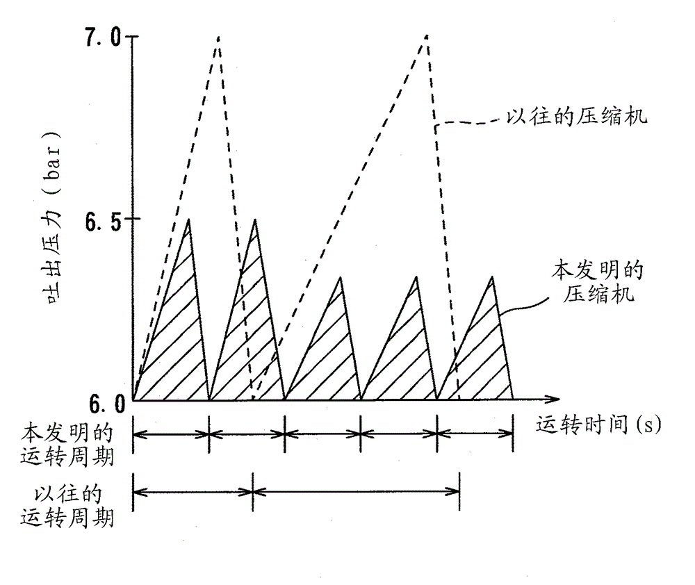
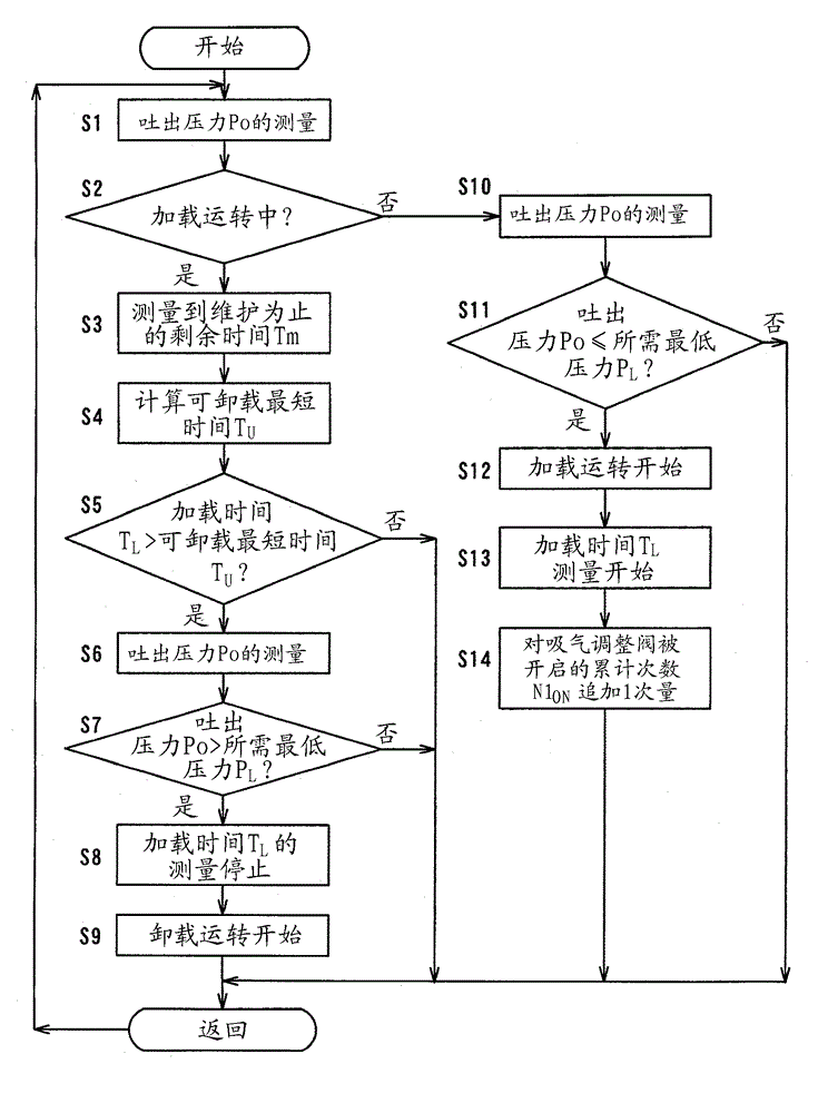
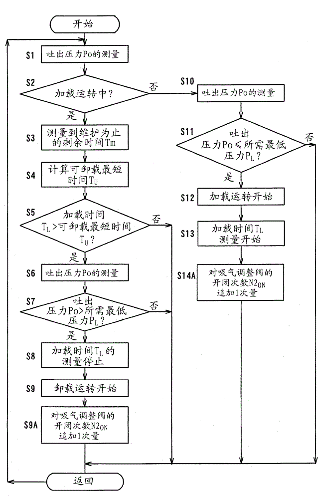
The invention provides a compressor and a pressure control method thereof, which can shorten the operation period, suppress the boosting during the loading operation, and perform the operation in an energy-saving way. The compressor includes an intake flow path (2), a suction adjusting valve (4) maintained after specified operation, a maintenance time measuring mechanism (11), a work time measuring mechanism (13), a loading operation time measuring mechanism (12), and a control mechanism (18) for switching the opening or closing of the suction adjusting valve. When the loading operation is under a discharge pressure greater than the lowest pressure required by the discharge side, the control mechanism switches the operation to unloading operation if the loading operation time measuring mechanism measures that the time lasting from the starting of the loading operation exceeds the shortest time for unloading. The shortest time for unloading is determined based on the residual time of the suction adjusting valve maintenance, the allowed work frequencies of the suction adjusting valve, and the cumulative work frequencies of the suction adjusting valve.

Description

technical field [0001] The invention relates to a compressor with a suction regulating valve and a pressure control method thereof. Background technique [0002] Conventionally, there is known a compressor that opens and closes a suction regulating valve provided in a suction flow path, and maintains the pressure of the discharge flow path, that is, the discharge pressure, at the required minimum pressure required on the load side by opening and closing. above, and by making the discharge pressure not higher than necessary, energy-saving operation is performed. In this compressor, when the discharge pressure becomes equal to or higher than the upper limit setting pressure, the suction regulating valve is closed (valve closed), the supply of suction gas to the compressor is stopped, and an unloaded operation state is established. On the other hand, when the discharge pressure is lower than the lower limit set pressure, the suction regulator valve is opened (valve open) to ma...

Claims


Application Information

Patent Timeline
Patent Type & Authority Applications(China)
IPC IPC(8): F04B49/22F04C28/24
Inventor 中西海
Owner 코벨코컴프레서가부시키가이샤
Why Eureka
Eureka Blog
Learn More