
Electric clamping plate

An electric splint and clip technology, which is applied to hair curlers, instant heating clips, clothing, etc., can solve the problems of inconvenient use of electric splints, inability to quickly cool down, and power cords affecting the effect of hair clipping.

Inactive Publication Date: 2015-03-18
SHAANXI PINGJIE SCI IND & TRADE
View PDF0 Cites 0 Cited by
  • Summary
  • Abstract
  • Description
  • Claims
  • Application Information

AI Technical Summary

Problems solved by technology

[0003] The purpose of the present invention is to overcome the problems that the existing electric splint is inconvenient to use when the power is cut off, the existence of the power cord affects the clipping effect, and the problem that it cannot be cooled quickly after use

Method used


Image

  • Electric clamping plate

Examples


Embodiment 1

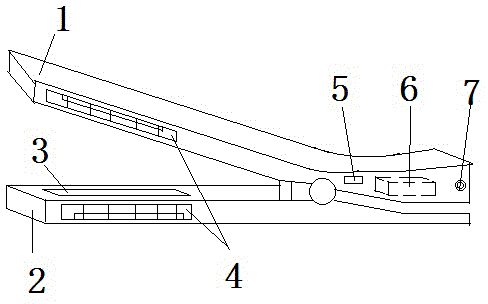
[0012] This embodiment provides a figure 1 The shown electric splint includes an upper clip 1 and a lower clip 2 whose rear ends are connected by a rotating shaft, and a heating plate 3 is arranged on the inner surfaces of the front ends of the upper clip 1 and the lower clip 2, and the upper clip 1 and the lower clip 2 The front end of the lower clip 2 is provided with a rectangular through hole, the rectangular through hole is placed between the heating plate 3 and the outer surface of the front end, a fan is arranged in the rectangular through hole, and the electric splint is set as a charging type, eliminating Without the power cord, the hair clipping effect is better because there is no obstacle of the power cord during the clipping process, and it can be used when the battery 6 is charged, so there is no need to worry about power failure. After the electric splint, the switch 5 can be used to control the opening of the fan to dissipate heat from the electric splint.

Embodiment 2

[0014] On the basis of Embodiment 1, the rear end of the upper clip 1 provided by this embodiment is provided with a battery 6, a switch 5 arranged on the rear end and a charging interface 7 connected to the battery 6, and the battery 6 passes through the switch 5. They are respectively connected to the heating plate 3 and the fan, and the opening of the rectangular through hole is provided with a ventilation grill 4 .

[0015] When the electric splint provided by the present invention is in use, when the switch 5 is in the closed state, the insertion end of the charging wire is directly inserted into the charging interface 7, and the battery 6 can be charged. Conductor, when needing to use this electric splint, directly open the switch that is used to control the work of heating plate 3 on the switch 5, can use its hairpin after waiting a little while, after the hairpin is finished, control the heat dissipation device again by switch 5 Just work.


PUM


Abstract

The invention provides an electric clamping plate. The electric clamping plate comprises an upper clamping piece and a lower clamping piece of which the rear ends are connected with each other through a rotating shaft; heating plates are arranged on the inner surfaces of the front ends of the upper clamping piece and the lower clamping piece; rectangular through holes are formed in the front ends of the upper clamping piece and the lower clamping piece and between the heating plates and the outer surfaces of the front ends; fans are arranged in the rectangular through holes. The electric clamping plate has the advantages that a storage battery, a switch and a charging interface are arranged, and a power cord is omitted, so that regardless of power on or power cut, all that is needed is to charge in advance, and the electric clamping plate can be used; during the use process, no interference of the power cord exists, so that the hair clamping effect is better; and after the electric clamping plate is used, the heating plates are cooled through the control of the switch, so that the heating plates can dissipate heat quickly and scalding to people can be avoided.

Description

technical field [0001] The invention belongs to household appliances, in particular to an electric splint. Background technique [0002] The existing electric splint can only provide the function of clamping hair, and it needs to be connected to the power supply through the power cord when in use, which brings inconvenience to the use of this product when the power is off, and the connection of the power cord will be damaged during the clipping process. Because the existence of the power cord affects the clipping effect, after the electric splint is used up, because it cannot be cooled in time, it is easy to cause bad consequences such as scalding people. Contents of the invention [0003] The purpose of the present invention is to overcome the problems that the existing electric splint is inconvenient to use when the power is cut off, the existence of the power cord affects the clipping effect, and the problem that it cannot be cooled quickly after use. [0004] For this...

Claims


Application Information

Patent Timeline
IPC IPC(8): A45D1/08
Inventor 吴华云
Owner SHAANXI PINGJIE SCI IND & TRADE
Learn More