Spring tensioning device comprising a universal tension table

A technology of spring clamping and clamping table, applied in the field of spring clamping devices, which can solve the problems of high purchase cost, maintenance cost, and space occupied by spring clamps

Active Publication Date: 2015-03-11
HAZET WERK HERMANN ZERVER
View PDF7 Cites 4 Cited by
  • Summary
  • Abstract
  • Description
  • Claims
  • Application Information

AI Technical Summary

Problems solved by technology

However, spring clamps of this type are particularly space-consuming and entail high acquisition and maintenance costs due to their complex function.

Method used


Image

  • Spring tensioning device comprising a universal tension table
  • Spring tensioning device comprising a universal tension table
  • Spring tensioning device comprising a universal tension table

Examples


Embodiment Construction

[0057] In the figures, the same reference symbols are used for identical or similar components, even if a repeated description is omitted for reasons of simplification.

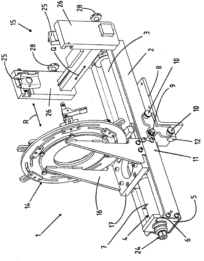
[0058] figure 1The spring clamping device 1 according to the invention is shown in a perspective side view from below in a horizontal operating position. The spring clamping device 1 has a profile rail 2 on which the components of the spring clamping device 1 are fixed decisively. Arranged inside the profiled rail 2 is a drive device 3 , which in the embodiment is formed by a movably inserted spring clamp 4 which is positively fastened inside the profiled rail 2 . For this purpose, transverse plates 5 are formed on the profiled rail 2 , the spring clamps 4 pass through recesses 6 in the transverse plates 5 in a form-fitting manner, and these transverse plates 5 are likewise received in a form-fitting manner on the inner peripheral surface 7 of the profiled rail 2 superior.

[0059] Thus profile 2 itself ha...


PUM


Abstract

The invention relates to a spring tensioning device (10) for mounting and / or removing helical compression springs on / from spring damper struts (57) for motor vehicles. According to the invention the spring tensioning device (1) comprises a universal tension table (14), wherein the spring damper strut (57) can be arranged such that the head plate (58) of the spring damper strut (57) is on the universal tension table (14) and the head plate (58) can be fixed in position by means of clamping shoes and brake arms (46).

Description

technical field [0001] The invention relates to a spring clamping device according to the features in the preamble of claim 1 for mounting or dismounting a helical compression spring on a shock absorber strut for a motor vehicle. [0002] The invention also relates to a spring clamping device according to the features in the preamble of claim 14 for assembling and / or dismounting a helical compression spring. Background technique [0003] The vehicle wheels are suspended on the vehicle axle in such a way that they can be sprung in or out in order to compensate for unevennesses in the road surface. Motor vehicles generally have a spring element and a damping element on each wheel for springing in or out. In the most common form of construction, the spring element is formed as a helical compression spring and, furthermore, the damping element is preferably integrated in the helical compression spring, so that the damping element is installed in the motor vehicle as a damper st...

Claims


Application Information

Patent Timeline
IPC IPC(8): B25B27/30
CPCB25B27/304
Inventor F·德布隆D·德特尔T·皮尔P·韦尔普
Owner HAZET WERK HERMANN ZERVER
Why Eureka
Try Eureka