Al technical title is built by PatSnap Al team. It summarizes the technical point description of the patent document.
A piston pump and self-priming technology, which is applied in the field of piston pumps, can solve the problems of residual medium leakage and evaporation, and the impossibility of heat preservation of the pump body, etc., and achieve the effects of compact structure, solving the problem of antifreeze and heat preservation, and small volume
Active Publication Date: 2015-03-11
任丘市本溪石油设备有限公司
View PDF8 Cites 2 Cited by
Summary
Abstract
Description
Claims
Application Information
AI Technical Summary
This helps you quickly interpret patents by identifying the three key elements:
Problems solved by technology
Method used
Benefits of technology
Problems solved by technology
When starting the pump for the second time, although the pump does not need to be primed, the residual medium is leaked and evaporated, and fluid replacement is still required to start the pump to absorb liquid
Regardless of whether it is a partial insulation interlayer or a full interlayer, the insulation is considered outside the contact with the medium, and the heat source needs to be provided from the outside. It is also necessary to set the mixing heat pipeline to connect with the pump body to achieve insulation. If the site does not have external Heat source medium, pump body insulation can not be achieved
Method used
Image
Click on the blue label to locate the original text in one second.
Reading with bidirectional positioning of images and text.
Examples
Embodiment Construction
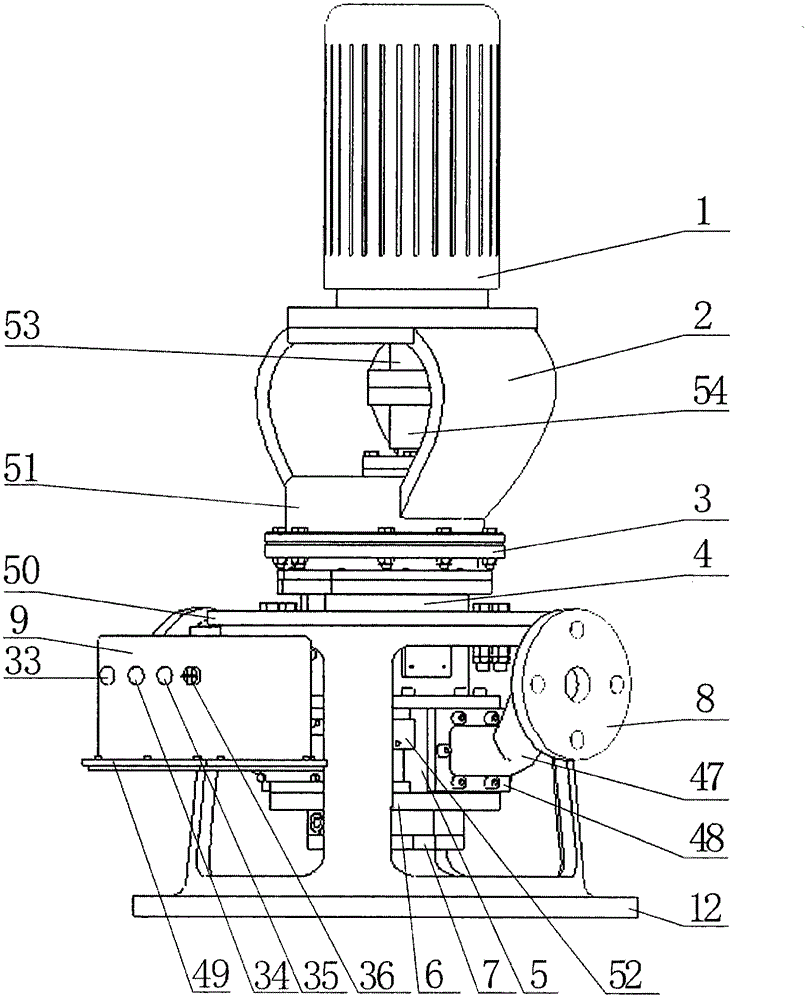
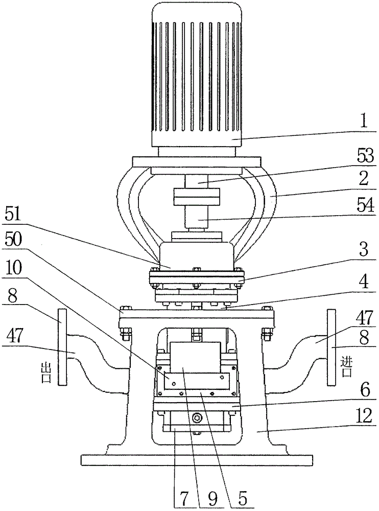
[0021] Such as figure 1 , figure 2 As shown, the upper part of the bracket 12 is connected with an outer bracket 50 by bolts, and the outer bracket 50 and the synchronous gear box 4 are integrally cast, and the synchronous gear box 4 is placed inside the bracket 12. The upper part is connected with the reduction box bearing seat 3 by bolts, and the reduction box bearing seat 3 is connected with the reduction box cover 51 set on the upper part by bolts. An explosion-proof motor 1 is fixed. A cavity 5 is provided at the bottom of the synchronous gearbox 4, and the cavity 5 is bolted to the synchronous gearbox 4 provided at the top and the cavity bearing seat 6 provided at the bottom, and a bearing is provided at the bottom of the cavity bearing seat 6. The seat end cover 7 is connected with flanges B48 at the inlet and outlet parts at both ends of the cavity 5 through bolts, and the cavity flow channel 52 is arranged in the inlet and outlet end faces of the cavity 5 . The in...
PUM
Abstract
The invention discloses a vertical anti-freezing self-priming piston pump. The vertical anti-freezing self-priming piston pump comprises a bracket, and an outer bracket positioned at the upper part of the bracket and formed integrally with a synchromesh gear case through casting. A reduction gearbox bearing base, a reduction gearbox cover, a motor bracket and an explosion-proof motor are arranged at the upper part of the synchromesh gear case in sequence. The vertical anti-freezing self-priming piston pump is characterized in that an upper sealing plate is arranged at the upper end of a cavity while a lower sealing plate is arranged at the lower end of the cavity; synchronous pistons are arranged between the upper sealing plate and the lower sealing plate; the two synchronous pistons are engaged with each other and rotate and the outer diameters of the pistons are in interference fit with the cavity; convex edges of upper and lower end surfaces are respectively in interference fit with the upper sealing plate and the lower sealing plate; an upper machine dynamic sealing ring, an upper machine static sealing ring, a lower machine dynamic sealing ring and a lower machine static sealing ring for sealing an auxiliary transmission shaft and a synchronous shaft are arranged at the upper parts and the lower parts of the synchronous pistons; and an electric heating water circulating device is disposed in an explosion-proof box at the upper part of a rear separated chamber of the cavity. The vertical anti-freezing self-priming piston pump has the advantages of small size, compact structure, good sealing performance and strong self-priming capacity, and effectively solves problems in freezing prevention and thermal insulation of a pump body.
Description
technical field [0001] The invention relates to a piston pump, in particular to a vertical antifreeze self-priming piston pump. Background technique [0002] In the practice of oilfield production, it is necessary to pump, dump, lift, and discharge media such as dirty oil and sewage. In this process, self-priming pumps are generally used to complete the process. Currently, known self-priming pumps, such as Chinese invention patents, The patent number is: 201210450786. It discloses an explosion-proof vertical self-priming pump, including explosion-proof motor, motor base, bearing seat, box body, pump cover, guide vane, impeller, main shaft, guide bearing, temperature measuring component, explosion-proof liquid level switch; the explosion-proof motor is installed on the motor seat, the bearing seat is installed on the box, and the motor shaft is connected to the pump main shaft with a diaphragm coupling. The main shaft is installed with metal bearings, mechanical seals, impel...
Claims
Application Information
Patent Timeline
Application Date:The date an application was filed.
Publication Date:The date a patent or application was officially published.
First Publication Date:The earliest publication date of a patent with the same application number.
Issue Date:Publication date of the patent grant document.
PCT Entry Date:The Entry date of PCT National Phase.
Estimated Expiry Date:The statutory expiry date of a patent right according to the Patent Law, and it is the longest term of protection that the patent right can achieve without the termination of the patent right due to other reasons(Term extension factor has been taken into account ).
Invalid Date:Actual expiry date is based on effective date or publication date of legal transaction data of invalid patent.