Mass transfer tray

A material exchange and tray technology, applied in chemical/physical processes, separation methods, chemical instruments and methods, etc., can solve the problems of uneven gas-liquid foam layer, insufficient effectiveness, and vacancies, and achieve high efficiency.

Active Publication Date: 2015-07-01
YURIUSU MONTSU
View PDF10 Cites 5 Cited by
  • Summary
  • Abstract
  • Description
  • Claims
  • Application Information

AI Technical Summary

Problems solved by technology

In such known mass exchange trays, it has been found that the gas-liquid foam layer (Sprudelschicht) formed by the trays is inhomogeneous and often has voids, so that the effectiveness achieved is insufficient.

Method used


Image

  • Mass transfer tray
  • Mass transfer tray
  • Mass transfer tray

Examples


Embodiment Construction

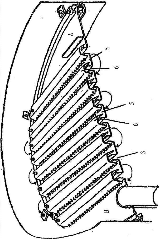
[0015] The mass exchange trays 1 according to the invention are installed horizontally in the column arrangement, wherein a plurality of trays 1 are arranged one above the other at a distance from each other. On each tray there is a liquid layer 2 through which the gas 4 flows from below through the gas passage gaps 3 . As a result, a gas-liquid foam layer consisting of liquid and gas bubbles forms above the tray 1 , in which gas-liquid foam layer an exchange of substances takes place. The liquid flows onto the tray on one side (inlet side A) on the edge of tray 1 in order to flow through the entire tray and exits on the other side (outlet side B) on the edge of the tray in order to reach the The tray below.

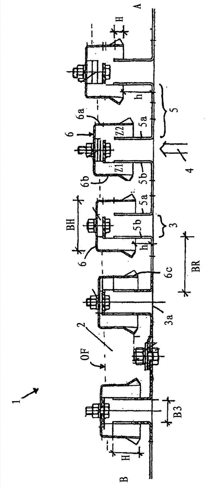
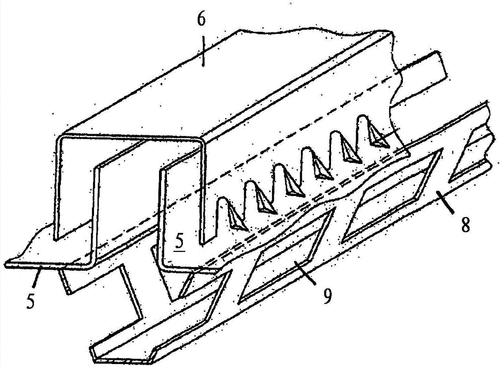
[0016] Between the inlet side A and the outlet side B, the tray consists of a plurality of mutually parallel, U-shaped profile-shaped grooves 5 in cross section, which form gas passage gaps 3 between them. Here, mutually facing, adjacent, vertical side walls 5 a , 5 b ...


PUM


Abstract

The invention relates to a mass transfer tray of a column with a liquid feed on the tray feed side and a liquid discharge on the opposite tray discharge side, and with multiple profile-shaped channels of a U-shaped cross section that are arranged in the tray between the feed and the discharge, parallel to one another and transversely in relation to the direction of liquid flow, and form between them gas passage slits which are covered over by elongated profile-shaped hoods, which have an inverted U-shaped cross section, wherein the side walls of the channels reach into the hoods, and so the channel side walls are covered over by the hood side walls by a height that is less than the height of the channel side walls and the height of the hood side walls, wherein the liquid flows alternately in opposite directions in the channels, and so in every second channel the liquid flows in one direction and in the channels lying in between the liquid flows in the opposite direction, and wherein the hoods are set higher than the channels in the case of the channels and hoods that are closer to the tray feed side, and consequently the heights over which they cover one another are less than in the case of the channels and hoods that are closer to the tray discharge side.

Description

technical field [0001] The invention relates to a material exchange tray / mass transfer tray of a column arrangement, having a liquid inlet on the inlet side of the tray and a liquid outlet on the outlet side of the opposite tray, and having a plurality of outlets between the inlet and the outlet Profile-shaped grooves arranged parallel to one another in the tray transversely to the direction of liquid flow, said grooves having a U-shaped cross-section, which form between them gas passage gaps, which are formed by elongated Covered by a profile-shaped casing having an inverted U-shaped cross-section, wherein the side walls of the groove protrude into the casing so that the groove side walls overlap the casing side walls to such a height that the The height is smaller than the height of the side wall of the groove and the height of the side wall of the casing. Background technique [0002] Such a substance exchange tray is known from DE 102 43 625 A1 and is described in the a...

Claims


Application Information

Patent Timeline
IPC IPC(8): B01D3/20
CPCB01D3/205B01D3/20B01F3/04078B01D3/324B01F23/214
Inventor H·扬森T·里特福特
Owner YURIUSU MONTSU
Why Eureka
Try Eureka