
a pumping aid

An oil pump and rotary mixer technology, applied in the field of pumping aids, can solve problems such as low liquid linear velocity

Active Publication Date: 2017-02-22
新疆赢华石油技术服务有限公司
View PDF6 Cites 0 Cited by
  • Summary
  • Abstract
  • Description
  • Claims
  • Application Information

AI Technical Summary

Problems solved by technology

But for the problem of low liquid linear velocity, there is no solution at home and abroad

Method used


Image

  • a pumping aid
  • a pumping aid
  • a pumping aid

Examples


Embodiment Construction

[0030] The technical solution of the present invention will be described in detail below in conjunction with the drawings and embodiments.

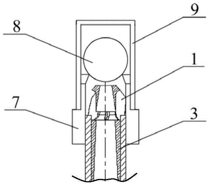
[0031] Such as figure 1 As shown, the embodiment of the present invention provides a pumping aid for use in an oil pump. The pumping aid includes: a screen 6, a liquid inlet cylinder 4, a rotary mixer 5, an oil pipe 2, a flow rate varying device 3, and an ejector 1.

[0032] Among them, the screen 6 is used to filter the produced fluid of the oil well.

[0033] The liquid inlet barrel 4 includes an upper section, a middle section and a lower section. The cross-sectional area of ​​the upper section of the liquid inlet barrel 4 gradually decreases with the flow direction of the oil well produced fluid. The lower section of the liquid inlet barrel 4 and the screen 6 Connected to the upper end.

[0034] The rotary mixer 5 is set in the liquid inlet cylinder 4, such as Figure 5 with Image 6 As shown, the rotary mixer 5 includes a rotating shaft 51 ...


PUM


Abstract

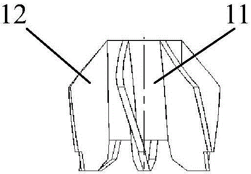
The invention discloses a pumping assistor used for an oil well pump. The pumping assistor comprises a sieve tube, a liquid inlet barrel, a rotary mixer, an oil tube, a flow rate changing device and an ejector, wherein the sieve tube is used for filtering oil well output liquid; the liquid inlet barrel comprises an upper section, a middle section and a lower section, and the lower section of the liquid inlet barrel is connected with the upper end of the sieve tube; the rotary mixer is arranged inside the liquid inlet barrel, and comprises a rotating shaft and blades arranged on the rotating shaft; the upper end of the oil tube is connected with a pump seat of the oil well pump, and the lower end of the oil tube is connected with the upper section of the liquid inlet barrel; the flow rate changing device is arranged inside the oil tube, and comprises at least one stage of flow rate transducer; the ejector is arranged at the top end of the oil tube and is positioned inside the pump seat; the ejector comprises an ejection barrel and a spiral plate arranged on the outer side of the ejection barrel. Under the precondition of unchanging formation pressure and feed liquid capacity, electricity is not used, namely the instant line speed of the oil well outlet liquid can be improved, so that pressure energy is changed into kinetic energy, the liquid flow rate is quickened, the liquid flow state is changed, the filling coefficient of the pump is improved, and the yield is increased.

Description

Technical field [0001] The present invention relates to the technical field of oil exploitation, in particular to a pumping aid used for an oil well pump. Background technique [0002] At present, more than 90% of oil wells in my country are pumped by pumps, but the pump type and pump diameter are different, regardless of which pump diameter is used, and the pump efficiency is lower than 50% on average. The main reasons that affect pump efficiency are: (1) Gas influence; the oil flow state is annular flow, with gas in the middle and oil in one circle. The bottom of the fixed valve forms a gas lock. After the valve is opened, the gas advances to the pump and takes up most of the space. , The oil enters the pump again, which seriously affects the full coefficient of the pump; (2) Friction resistance; Because of the high viscosity and friction of crude oil, it affects the amount of liquid into the pump, resulting in low pump efficiency; (3) The flow area of ​​the oil pipe is too lar...

Claims


Application Information

Patent Timeline
Patent Type & Authority Patents(China)
IPC IPC(8): E21B43/00F04B53/00
CPCE21B43/121F04B53/00
Inventor 姜飞
Owner 新疆赢华石油技术服务有限公司
Learn More