
Gear shaft pressing clamp

A technology for gear shafts and fixtures, which is applied in the manufacture of tools, workpiece clamping devices, metal processing, etc., can solve the problem of no mechanism to detect the verticality of gears and shafts, so as to avoid scrapping, improve the pass rate, and good positioning effect Effect

Inactive Publication Date: 2015-03-11
CHONGQING WEIHAO GEAR
View PDF0 Cites 2 Cited by
  • Summary
  • Abstract
  • Description
  • Claims
  • Application Information

AI Technical Summary

Problems solved by technology

[0004] The invention provides a gear shaft pressing fixture to solve the problem that there is no mechanism to detect the perpendicularity between the gear and the shaft during the pressing process

Method used


Image

  • Gear shaft pressing clamp

Examples


Embodiment Construction

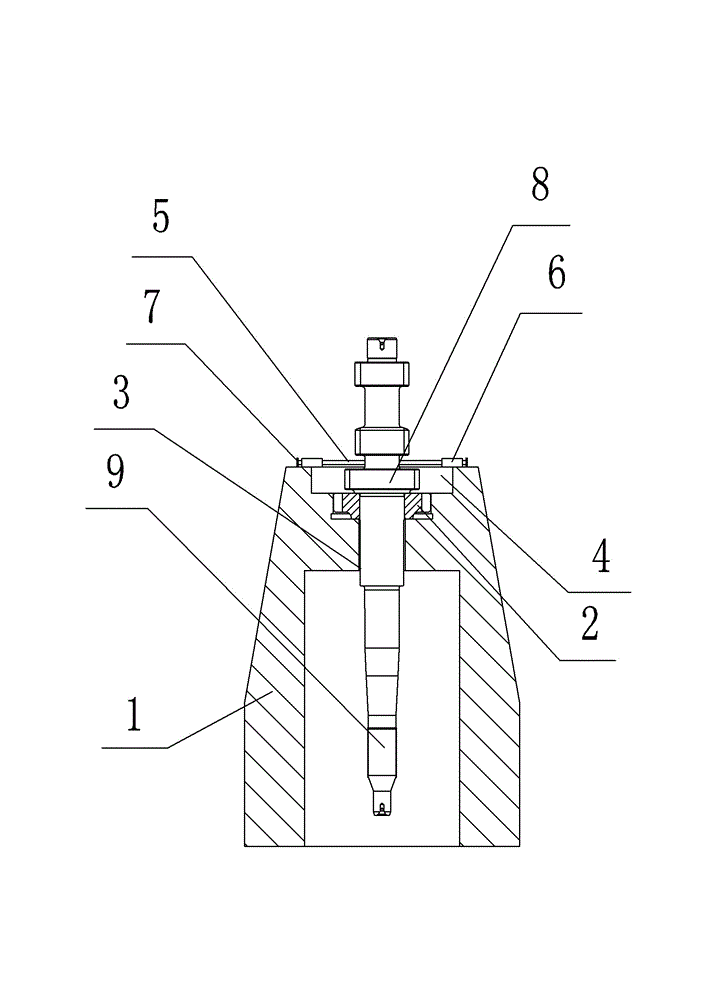
[0014] The reference signs in the drawings of the specification include: base 1 , positioning ring 2 , through hole 3 , groove 4 , detection rod 5 , positioning block 6 , safety pin 7 , gear 8 , and shaft body 9 .

[0015] Such as figure 1 As shown, a gear shaft pressing fixture in this embodiment includes a base 1 and a positioning ring 2. The base 1 is provided with a through hole 3 for accommodating the shaft body 9 and a groove 4 for accommodating the gear 8. The positioning ring 2 is provided with in groove 4. It also includes a guide device arranged on the base 1 opposite to the center of the through hole 3 , the guide device includes a detection rod 5 , a positioning block 6 located above the groove 4 and a safety pin 7 . There is a through hole 3 in the positioning block 6, and the detection rod 5 is movably connected in the through hole 3. The end of the detection rod 5 close to the shaft body 9 extends to the theoretical outer contour of the shaft body 9, and the en...


PUM


Abstract

The invention discloses a gear shaft pressing clamp. The gear shaft pressing clamp comprises a base, a positioning device and a guide device, wherein a through hole for accommodating a shaft body and a groove for accommodating a gear are formed in the base; the positioning device is arranged in the groove; the guide device is arranged on the base; the guide device comprises a detecting rod, a positioning block positioned above the groove and a safety pin; a through hole is formed in the positioning block; the detecting rod is movably connected to the interior of the through hole; one end of the detecting rod is in contact with the shaft body; the other end of the detecting rod is pressed against the safety pin. According to the gear shaft pressing clamp, whether the shaft body is perpendicular to the end surface of the gear can be determined through the safety pin; when the shaft body is not perpendicular to the gear, the safety pin can be ejected out. At the moment, the shaft body is not inserted into the gear, and the gear can be prevented from being pressed askew if an oil press is stopped in time, so that a gear shaft is prevented from being scrapped because the gear is pressed askew; therefore, the pass rate of the gear shaft is improved.

Description

technical field [0001] The present invention belongs to the technical field of press-fit connection. Background technique [0002] When pressing the gear on the shaft body, it is a common technology in the automotive industry. When pressing the gear, the gear needs to be heated and positioned, and then the shaft body passes through the gear. When the gear cools down, there is an interference between the gear and the shaft body Cooperate, the gear is not easy to fall off from the shaft body. [0003] The existing clamping fixture only includes a positioning device for fixing the gear. The shaft is pushed by a hydraulic press. When the shaft moves towards the gear, there is no mechanism to detect the perpendicularity between the gear and the shaft. In this way, it is impossible to ensure that the gears can be straightened. If the straightening cannot be done, the workpiece will be scrapped, and the pass rate of the workpiece will be affected. Contents of the invention [0...

Claims


Application Information

Patent Timeline
Patent Type & Authority Applications(China)
IPC IPC(8): B25B11/02B23P19/027
CPCB25B11/02B23P19/027
Inventor 张恒瑞
Owner CHONGQING WEIHAO GEAR
Learn More