
Automatic feeding device

A technology of automatic feeding and feeding plate, applied in metal processing and other directions, can solve the problems of high production cost, deviation of material axial feeding position, inability to meet positioning feeding, etc., to overcome single use function, meet processing requirements, and high positioning accuracy. Effect

Active Publication Date: 2015-03-11
SHENZHEN JINZHOU PRECISION TECH
View PDF6 Cites 18 Cited by
  • Summary
  • Abstract
  • Description
  • Claims
  • Application Information

AI Technical Summary

Problems solved by technology

[0003] However, the traditional hopper can only hold a single length of material. When the length of the material changes, it needs to be redesigned, and the production cost is high.
In addition, the traditional feeding mechanism pushes the material along the axial direction of the material. Due to the influence of the material's motion inertia, there is a large deviation in the axial feeding position of the material.
However, for equipment with high requirements on the feeding position, it cannot meet the requirements of positioning and feeding.

Method used


Image

  • Automatic feeding device
  • Automatic feeding device
  • Automatic feeding device

Examples


Embodiment Construction

[0019] In order to make the objectives, technical solutions and advantages of the present invention clearer, the following further describes the present invention in detail with reference to the accompanying drawings and embodiments. It should be understood that the specific embodiments described herein are only used to explain the present invention, but not to limit the present invention.

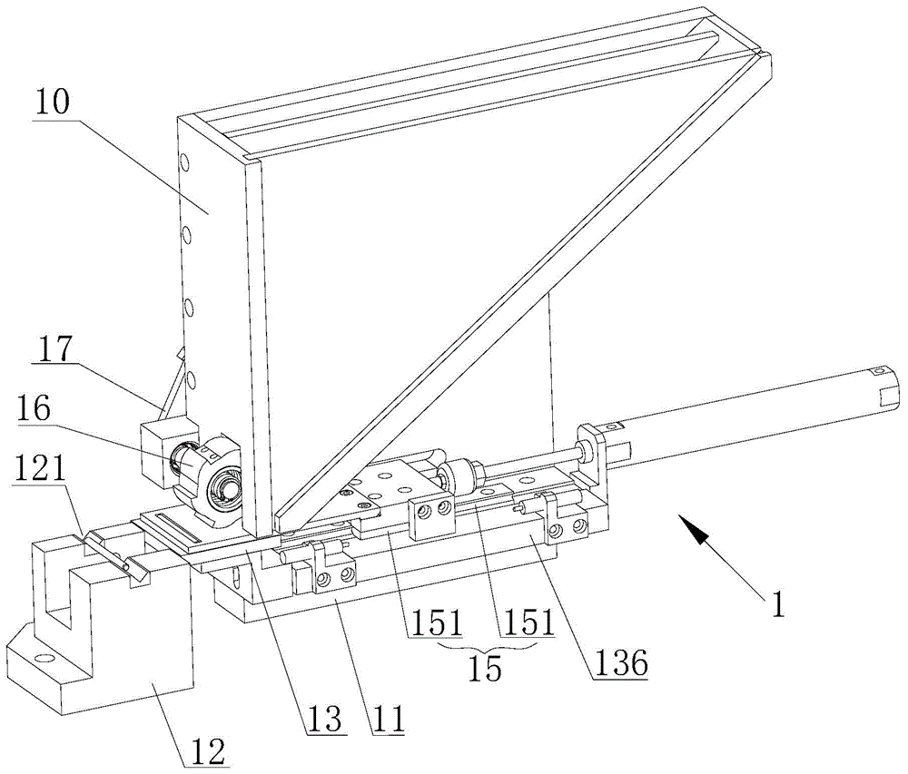
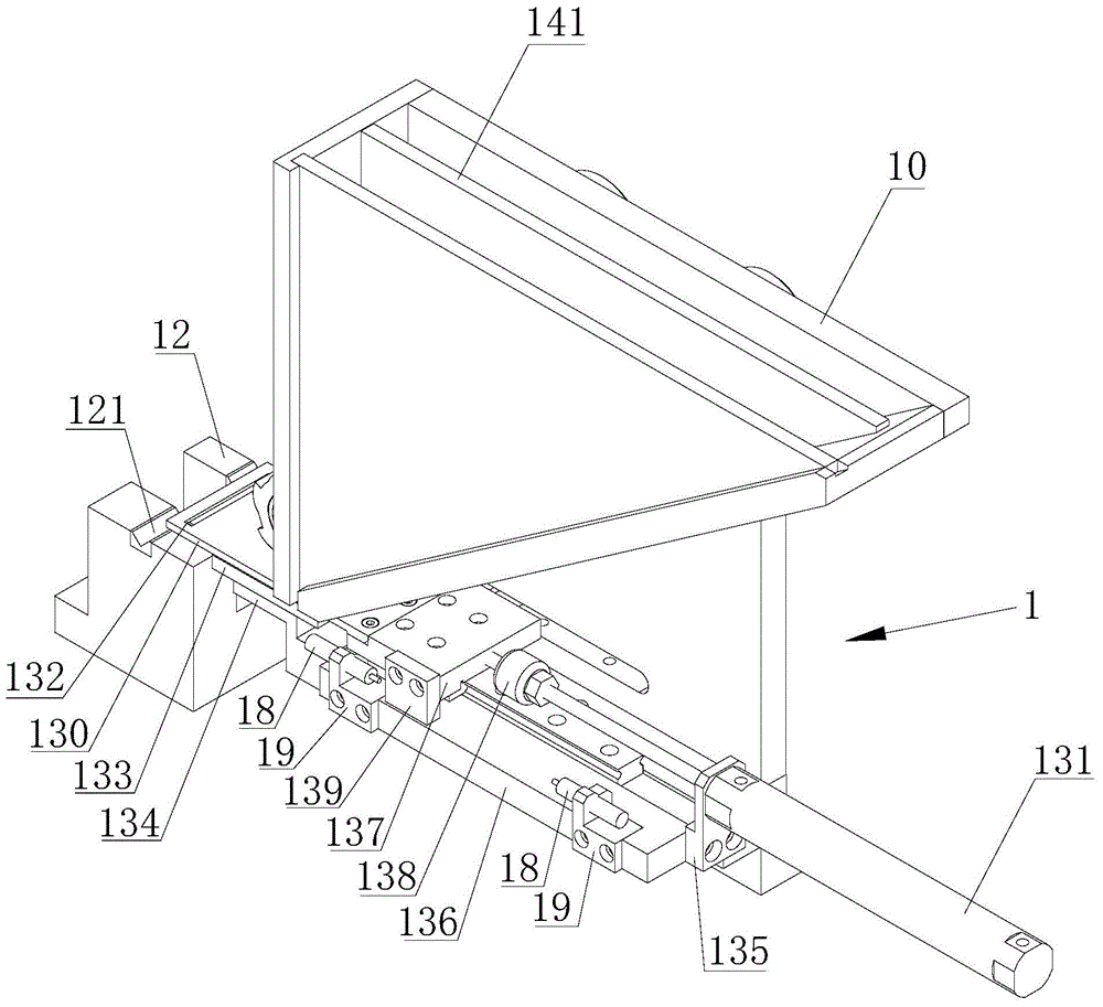
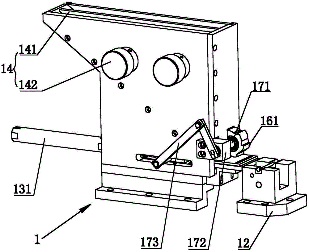
[0020] Such as figure 1 As shown, an automatic feeding device 1 provided by an embodiment of the present invention includes a hopper 10 for holding materials to be processed and a mounting seat 11 arranged below the hopper 10. The shape of the hopper 10 is triangular, and the bottom side is set to be inclined The sloping surface of the hopper 10 (not shown in the figure) is set at the bottom of the sloping surface, so that the material to be processed in the hopper 10 can automatically flow to the discharge port without additional components to drive the Processing material movement.

[0021] ...


PUM


Abstract

The invention applies to the technical field of machining equipment and discloses an automatic feeding device which comprises a hopper used for containing a material to be machined, and a mounting seat arranged below the hopper, wherein the hopper has an inclined plane, and a discharge hole of the hopper is formed in the bottom part of the inclined plane; the mounting seat is provided with a feeding component used for conveying the material to be machined onto a machining position; the hopper is provided with an adjustment component used for adjusting the size of a containing cavity of the hopper. According to the automatic feeding device provided by the invention, the size of the containing cavity of the device can be adjusted, so that materials with different sizes can be contained; the automatic feeding device is complete in using functions, and the feeding component is high in material conveying location accuracy, and capable of accurately conveying the material onto the machining position, so that the using requirement of high accuracy location for the material can be met.

Description

Technical field [0001] The invention belongs to the technical field of machining equipment, and in particular relates to an automatic feeding device. Background technique [0002] In the field of mechanical processing, it is usually necessary to set up a hopper to contain the materials to be processed, and accordingly set up a feeding mechanism to convey the materials, so as to improve the convenience and efficiency of processing. For example, the material flexural strength testing equipment is provided with a hopper and a feeding mechanism for holding materials, so that several materials can be continuously tested, and the testing efficiency is high. [0003] However, the traditional hopper can only hold a single length of material. When the length of the material changes, it needs to be redesigned and the production cost is high. In addition, the traditional feeding mechanism pushes the material along the axial direction of the material. Due to the influence of the inertia of th...

Claims


Application Information

Patent Timeline
Patent Type & Authority Applications(China)
IPC IPC(8): B23Q7/00B23Q7/10
CPCB23Q7/00B23Q7/10
Inventor 朱建
Owner SHENZHEN JINZHOU PRECISION TECH
Learn More