Tool changing post

A tool holder and fixture seat technology, which is applied in the field of tool changer, can solve the problems of cumbersome tool change process, difficulty in ensuring the coaxiality of hole machining, and time-consuming

Inactive Publication Date: 2015-03-11
CHANGZHOU ZHUJIANG TOOL
View PDF0 Cites 1 Cited by
  • Summary
  • Abstract
  • Description
  • Claims
  • Application Information

AI Technical Summary

Problems solved by technology

[0002] The workpiece often needs to be holed. For more complex hole processing, different tools are usually used. It is difficult to ensure the coaxiality of the h

Method used


Image

  • Tool changing post
  • Tool changing post
  • Tool changing post

Examples


Embodiment Construction

[0015] The present invention will be further described below in conjunction with the accompanying drawings and specific embodiments.

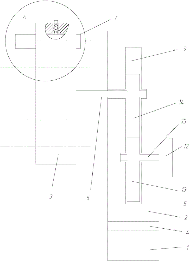
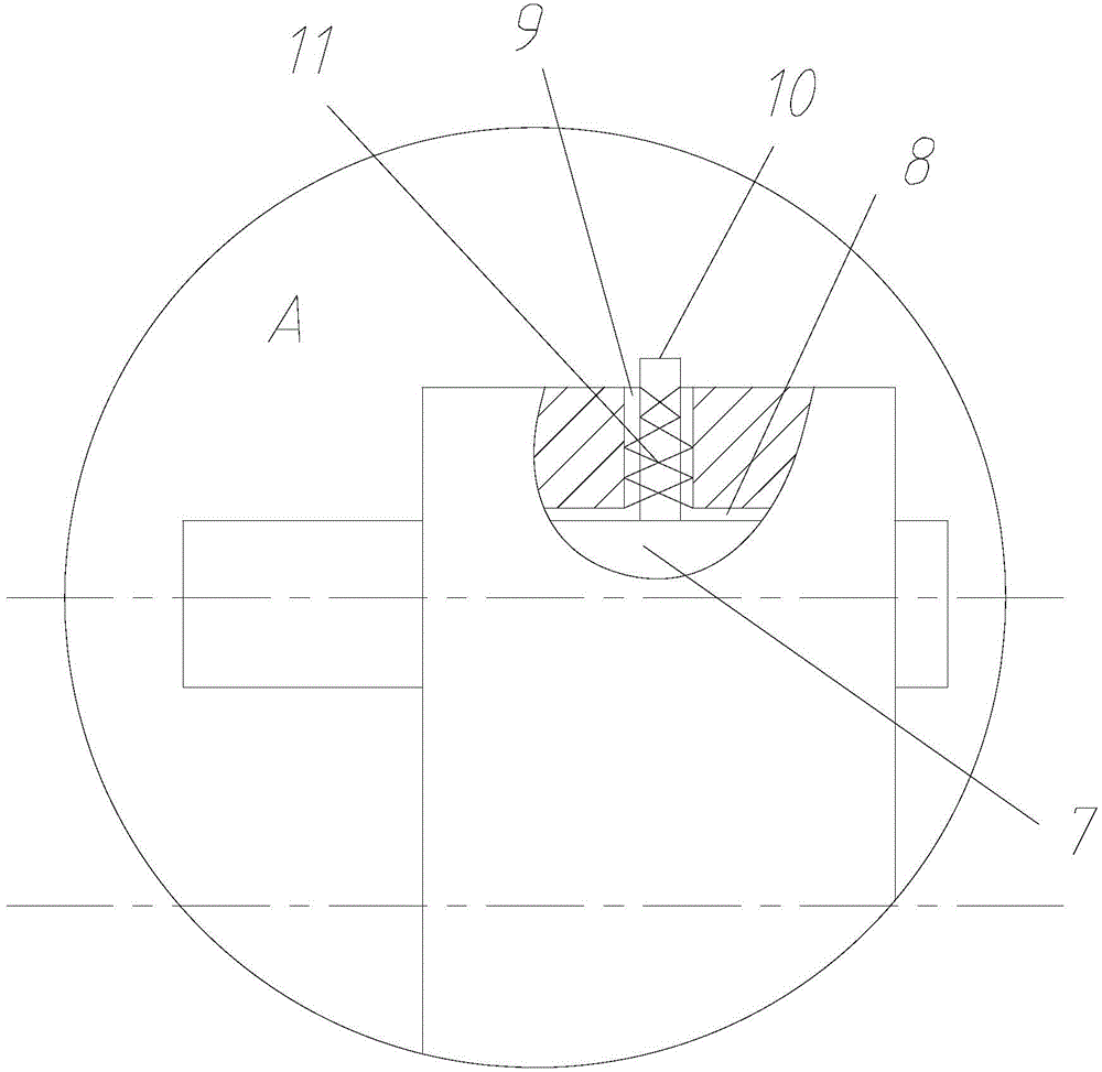
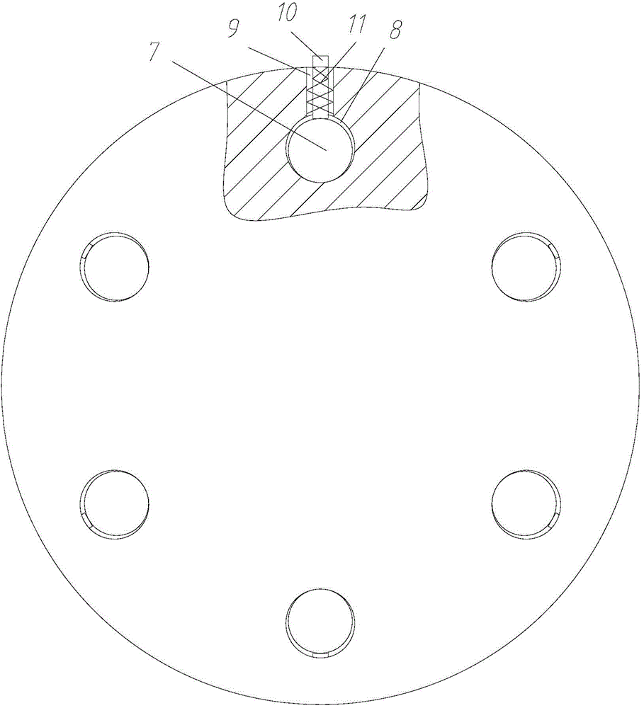
[0016] see Figure 1~3 , a tool changer, comprising a base 1 that can move back and forth, left and right, a fixture seat 2 that can move up and down on the base, and a rotatable fixture 3 that is arranged on one side of the fixture seat. There is a lifting mechanism 4 connected between them, the interior of the clamp seat is provided with an accommodating cavity 5 for accommodating the transmission mechanism, and the side wall on one side of the clamp seat is provided with a transmission shaft 6 connected with the transmission mechanism, and the clamp is cylindrical , the fixture is provided with a number of axially arranged through holes 8 for placing the cutter 7, the through holes are evenly distributed around the axis of the fixture, the side wall of the fixture is provided with a locking mechanism for locking the cutter, the fixture and t...


PUM


Abstract

The invention relates to a tool changing post. The tool changing post comprises a base capable of moving back and forth, and left and right, a fixture seat arranged on the base and capable of moving up and down, a rotatable fixture arranged on one side of the fixture seat; a lifting mechanism is connected between the base and the fixture seat; a receiving cavity for receiving a transmission mechanism is arranged inside the fixture seat; a transmission shaft connected with the transmission mechanism is arranged on the sidewall of one side of the fixture seat; the fixture is cylindrical; a plurality of through holes for holding cutting tools are formed in the fixture in the axial direction; the through hole are distributed evenly around the axis of the fixture; a locking mechanism for locking the cutting tools is arranged on the sidewall of the fixture; the fixture is connected with the fixture seat by use of a transmission shaft; the transmission shaft is coaxial with the fixture, and the transmission shaft is perpendicular to the sidewalls of the fixture seat. The tool changing post has the advantages that the coaxality of hole machining after tool changing is guaranteed, and meanwhile, the trouble of tool re-setting after tool changing is avoided, the time taken by tool changing is shortened and the tool changing rate is greatly increased.

Description

technical field [0001] The invention relates to the technical field of mechanical tools, in particular to a tool changer. Background technique [0002] The workpiece often needs to be holed. For more complex hole processing, different tools are usually used. It is difficult to ensure the coaxiality of the hole processing for multiple tool changes, and most of the tool changes are manual tool changes. The tool change process is cumbersome and difficult. time consuming. Contents of the invention [0003] In view of the above problems, the object of the present invention is to provide a tool changer that can realize quick tool change. [0004] Realize the technical scheme of the present invention as follows: [0005] A tool changer, comprising a base that can move back and forth, left and right, a fixture seat that can move up and down on the base, and a rotatable fixture that is set on one side of the fixture seat. mechanism, the inside of the fixture seat is provided wit...

Claims


Application Information

Patent Timeline
IPC IPC(8): B23Q3/155
CPCB23Q3/155B23Q3/1552
Inventor 吴美蓉
Owner CHANGZHOU ZHUJIANG TOOL
Why Eureka
Try Eureka