
Automatic brazing material paving and spot welding system and control method thereof

A brazing material and spot welding technology, which is applied in the field of metal resistance welding, can solve problems such as difficulties and achieve the effects of prolonging service life, realizing positioning, improving adaptability and automation level

Active Publication Date: 2015-03-11
AMET WELDING AUTOMATION TECH BEIJING
View PDF7 Cites 5 Cited by
  • Summary
  • Abstract
  • Description
  • Claims
  • Application Information

AI Technical Summary

Problems solved by technology

[0004] The present invention designs an automatic brazing material laying spot welding system and its control method. The technical problem it solves is to use machines instead of manpower to fix the solder spot welding on the welding surface to realize automatic production. Due to the position and leveling of the solder High precision requirements, it is difficult to lay solder on a large curved surface

Method used


Image

  • Automatic brazing material paving and spot welding system and control method thereof
  • Automatic brazing material paving and spot welding system and control method thereof
  • Automatic brazing material paving and spot welding system and control method thereof

Examples


Embodiment Construction

[0043] Combine below Figure 1 to Figure 8 , the present invention is further described:

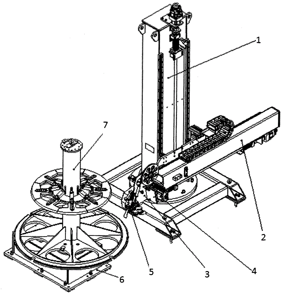
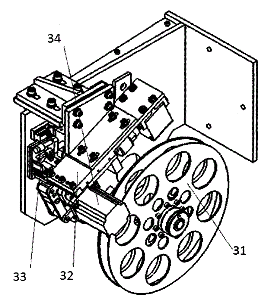
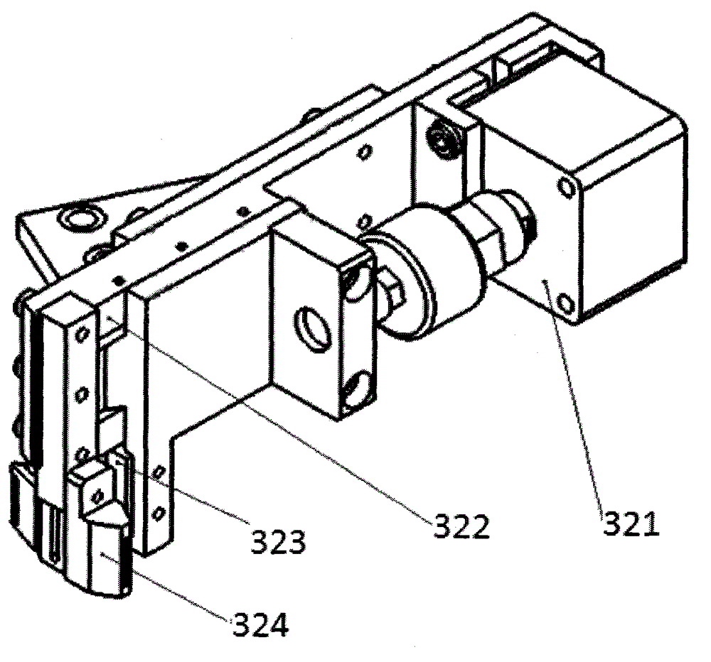
[0044] Such as figure 1 As shown, an automatic brazing material laying spot welding system includes a column 1, a moving beam 2, a spot welding head 3, a horizontal slide 4 and a turntable 6. One end of the moving beam 2 is connected to the spot welding head 3; the moving beam 2 moves horizontally on the column 1 driven by a servo motor, and the moving beam 2 moves vertically on the column 1 driven by another servo motor; The spot welding head 3 moves horizontally on the horizontal sliding table 4 driven by the third servo motor; the tooling 7 is arranged on the rotary table 6, and the welding workpiece is fixed on the tooling 7, and the tooling 7 and the rotary table 6 pass through the fourth servo Rotate driven by motor.

[0045] The moving beam 2 can move horizontally or vertically, and is driven by a servo motor, which is controlled by a CNC numerical control system. Different pro...


PUM


Abstract

The invention relates to an automatic brazing material paving and spot welding system and a control method thereof. The automatic brazing material paving and spot welding system comprises an upright post (1), a movable beam (2), a spot welding machine head (3), a transverse slide table (4) and a rotary table (6) and is characterized in that one end of the movable beam (2) is connected with the spot welding machine head (3); the movable beam (2) is driven to move horizontally in the horizontal direction on the upright post (1) through a servo motor, and the movable beam (2) is driven to move in the vertical direction on the upright post (1) through another servo motor; the spot welding machine head (3) is driven to move horizontally on the transverse slide table (4) in the horizontal direction through a third servo motor; the rotary table (6) is provided with a fixture (7), a weld workpiece is fixed on the fixture (7), and the fixture (7) and the rotary table (6) are driven to rotate through a fourth servo motor; weld strips output from the spot welding machine head (3) cover ribs of the workpiece, and the weld strips are welded and fixed transversely or longitudinally.

Description

technical field [0001] The invention relates to the field of metal resistance welding, in particular to an automatic brazing material laying spot welding system and a control method thereof before vacuum brazing of stainless steel. Background technique [0002] For vacuum brazing with a large welding area, it is required to lay the brazing material on the welding surface before welding. At present, there is no equipment for laying solder automatically. The common method is to manually fix the solder spot welding on the welding surface. Due to the high requirements on the position and flatness of the solder, it is difficult to lay the solder on a curved surface with a large area. [0003] In order to achieve automatic laying of solder and improve the level of welding technology, our company has set up a project to develop an automatic spot welding system for this application. Contents of the invention [0004] The present invention designs an automatic brazing material la...

Claims


Application Information

Patent Timeline
IPC IPC(8): B23P23/04B23K3/06B23K3/08
CPCB23K3/08
Inventor 张洪涛罗金辉王中亚
Owner AMET WELDING AUTOMATION TECH BEIJING
Learn More