
Compressive sensing SAR sparse self-focusing imaging method with optimum image entropy

An imaging method, self-focusing technology, applied to the reflection/re-radiation of radio waves, the use of re-radiation, measurement devices, etc.

Inactive Publication Date: 2015-03-04
UNIV OF ELECTRONICS SCI & TECH OF CHINA
View PDF5 Cites 18 Cited by
  • Summary
  • Abstract
  • Description
  • Claims
  • Application Information

AI Technical Summary

Problems solved by technology

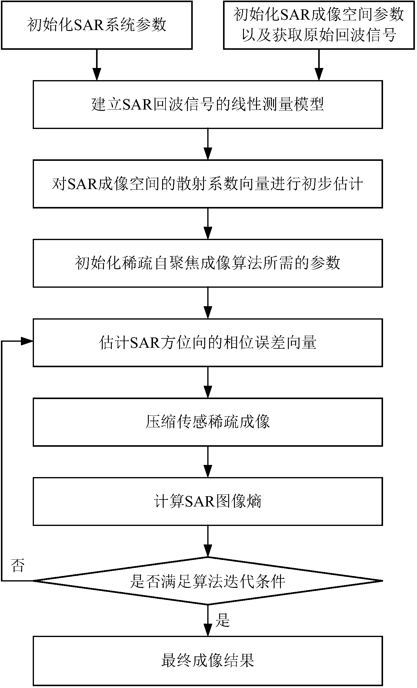
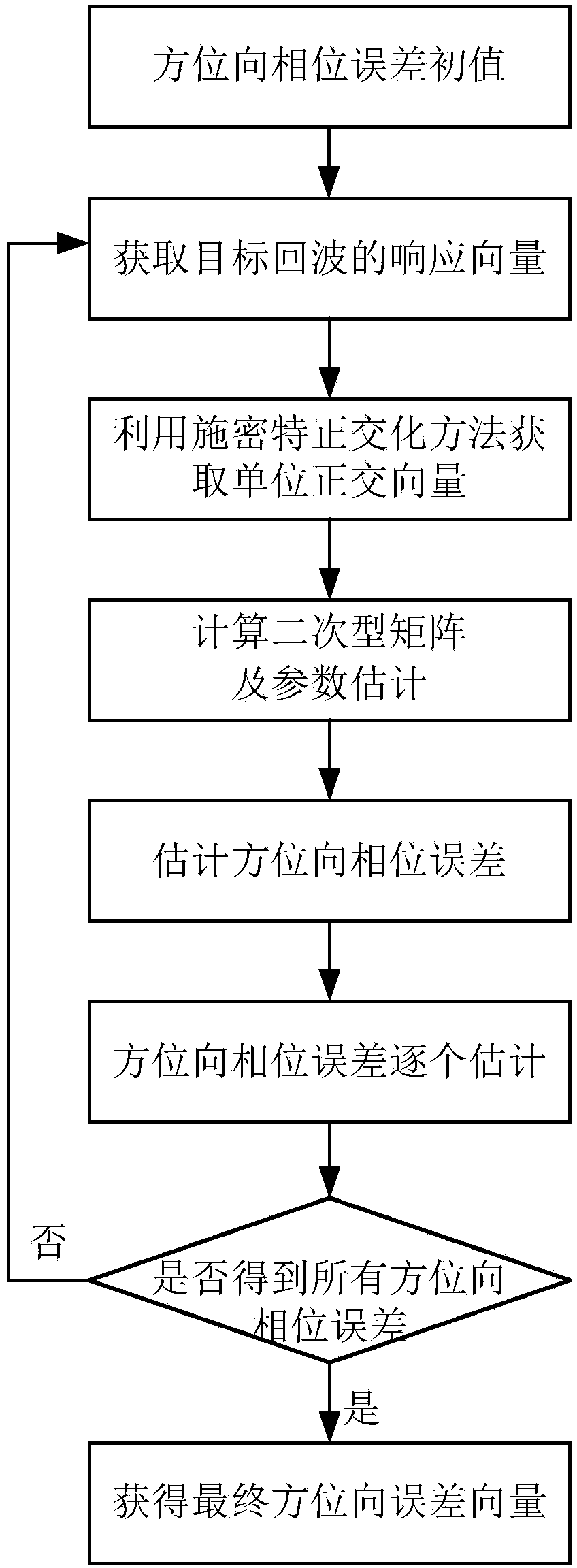
[0004] In order to solve the problem of estimation and compensation of unknown azimuth phase error in the compressed sensing SAR sparse imaging process, the present invention combines the compressed sensing sparse reconstruction method and SAR image entropy, a compressed sensing SAR sparse self-focusing imaging method with optimal image entropy is proposed. The present invention uses the azimuth phase error characteristics and sparse target features in the imaging model, and uses compressed sensing SAR image entropy as an evaluation criterion. A compressive sensing SAR sparse self-focusing imaging method with optimal image entropy is proposed. In each iterative process, the method uses the relationship between the SAR azimuth echo and the observation target to estimate the azimuth phase error, and then compressive sensing The imaging model performs phase error compensation, and then compressive sensing SAR imaging is performed, and the successive iteration method is used to optimize the image entropy of compressive sensing SAR imaging, thereby improving the quality of compressive sensing SAR imaging

Method used


Image

  • Compressive sensing SAR sparse self-focusing imaging method with optimum image entropy
  • Compressive sensing SAR sparse self-focusing imaging method with optimum image entropy
  • Compressive sensing SAR sparse self-focusing imaging method with optimum image entropy

Examples


Embodiment Construction

[0081] The present invention mainly adopts the method of simulation experiment to verify, and all steps and conclusions are verified on MATLABR2008b software. The specific implementation steps are as follows:

[0082] Step 1. Initialize SAR system parameters:

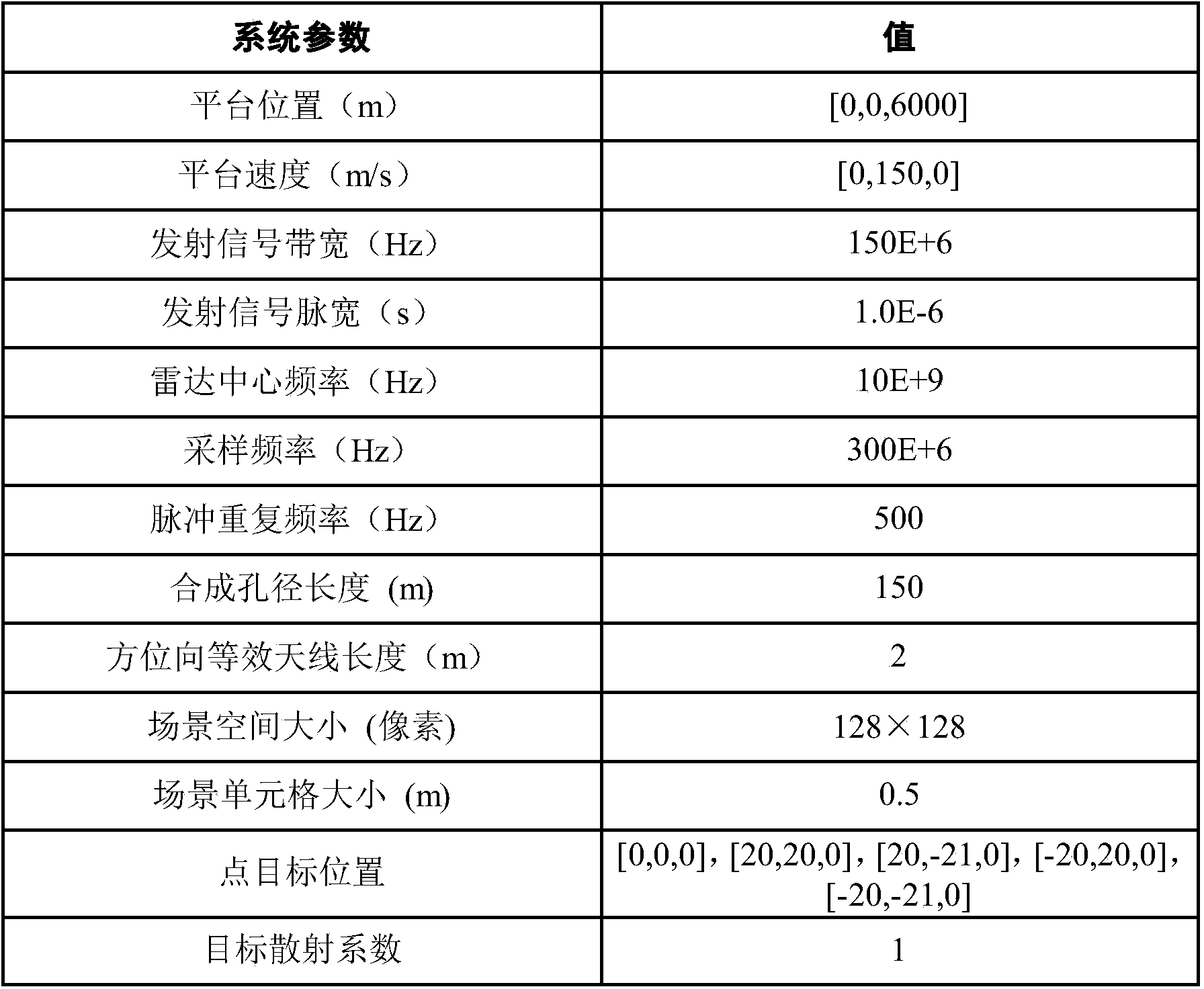
[0083] Initialize SAR system parameters include: platform velocity vector V=[0,150,0]m / s; antenna initial position vector P(0)=[0,0,6000]m; radar working center frequency f c =10×10 9 Hz; radar carrier frequency wavelength λ = 0.03m; signal bandwidth B of radar transmitting baseband signal r =1.5×10 8 Hz; Radar transmit signal pulse width T P =1×10 -6 s; the frequency modulation slope f of the radar transmitted signal dr =1.5×10 14 Hz / s; the sampling frequency f of the radar receiving system s =3×10 8 Hz; radar pulse repetition frequency PRF = 500Hz; the equivalent antenna length in azimuth is D a =2m; the propagation speed of light in air C=3×10 8 m / s; the total number of fast moments in distance N R =128, ...


PUM


Abstract

The invention discloses a compressive sensing SAR sparse self-focusing imaging method with optimum image entropy. The method is targeted for the influence of azimuth phase errors in a SAR echo signal measurement model on compressive sensing SAR imaging, and the problem of estimation and compensation of unknown phase errors in a compressive sensing SAR imaging model; azimuth phase error characteristics and sparse target characteristics in the imaging model are utilized, and compressive sensing SAR image entropy is adopted as an evaluation criteria; relationship of SAR azimuth echoes and observed objects are utilized to estimate the azimuth phase errors in each iteration processing process; then, phase error compensation is carried out on the compressive sensing imaging model; and next, compressive sensing SAR imaging is carried out, and a successive iteration method is utilized to enable the image entropy of the compressive sensing SAR imaging to be optimum, thereby improving compressive sensing SAR imaging quality.

Description

Technical field: [0001] The technical invention belongs to the technical field of radar, and in particular relates to the technical field of synthetic aperture radar (SAR) imaging. Background technique: [0002] Due to its advantages of all-weather, all-weather and large-scale scene observation, synthetic aperture radar (SAR) has become an important remote sensing technology for large-area topographic surveying and mapping. greater effect. Compressed sensing sparse reconstruction, as a newly proposed signal processing theory in recent years, breaks through the constraints of the traditional Nyquist sampling theorem, and can accurately reconstruct the original sparse signal with a sampling rate much lower than that of Nyquist (see reference "D.L.Donoho. Compressed sensing. IEEE Transactions on Information Theory, 2006, 52(4): 1289-1306”), has great application potential in reducing the sampling rate of SAR systems and improving imaging quality. Therefore, compressive sensin...

Claims


Application Information

Patent Timeline
IPC IPC(8): G01S13/90
CPCG01S13/90G01S13/904G01S13/9019
Inventor 韦顺军张晓玲熊海进
Owner UNIV OF ELECTRONICS SCI & TECH OF CHINA
Learn More