
Two-fluid atomization nozzle

An atomizing nozzle and two-fluid technology, which is applied in the direction of liquid injection devices, injection devices, etc., can solve the problem of reducing the service life of atomizing components, it is difficult to ensure the atomization rate and atomization degree of wastewater, and the atomizing components are easily corroded and damaged. question

Active Publication Date: 2015-03-04
YICHUAN TECH CHENGDU CO LTD
View PDF7 Cites 29 Cited by
  • Summary
  • Abstract
  • Description
  • Claims
  • Application Information

AI Technical Summary

Problems solved by technology

[0002] The industrial wastewater evaporation process requires the evaporated wastewater to be completely atomized to meet the complete evaporation of the wastewater into gaseous water vapor in a fixed-time or fixed-length space. However, the atomization components that have been in contact with the wastewater for a long time are easily corroded and damaged. Therefore, the fog is reduced. In particular, the nozzles in the prior art are mostly integrated structures. After the atomization components are corroded and damaged, the atomization nozzles can only be replaced as a whole, and the cost is relatively high.
[0003] In addition, in the prior art, there is no atomization nozzle specially designed for wastewater. It is difficult for traditional atomization nozzles to guarantee the atomization rate and atomization degree of wastewater. Therefore, it is urgent to develop a new technical solution to solve the above problems.

Method used


Image

  • Two-fluid atomization nozzle
  • Two-fluid atomization nozzle
  • Two-fluid atomization nozzle

Examples


Embodiment Construction

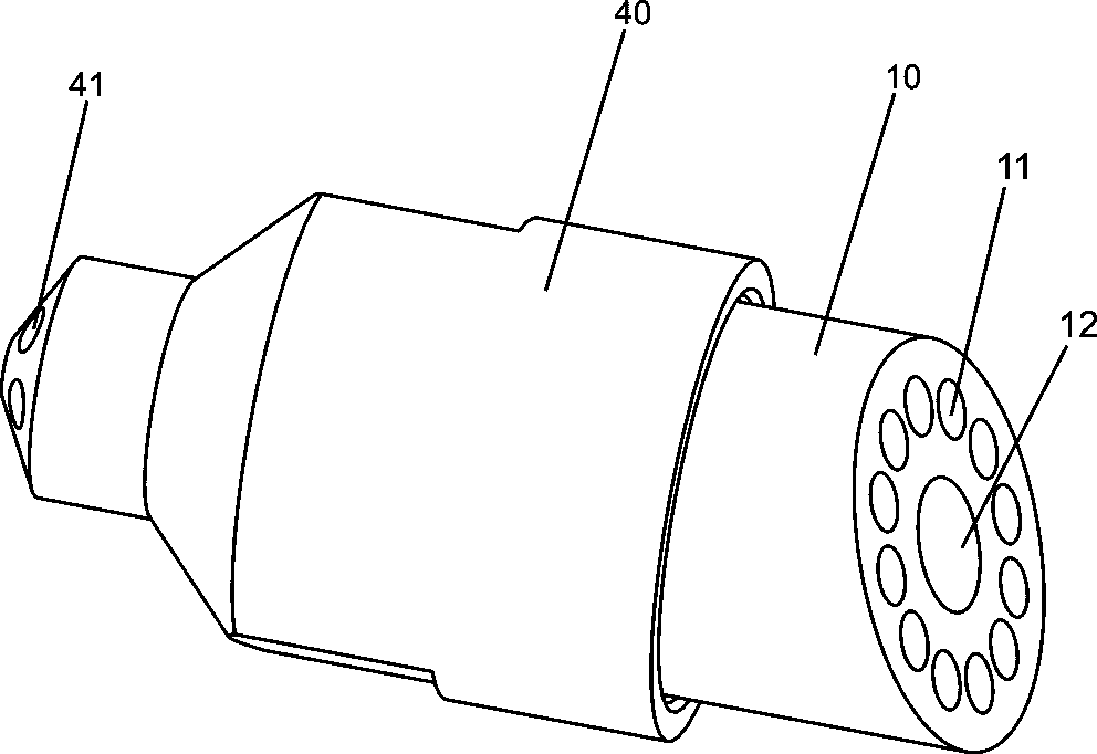
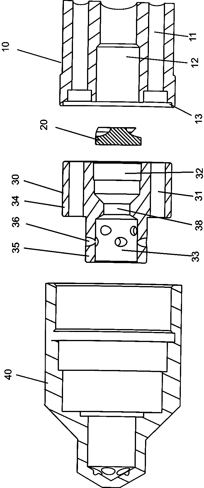
[0037] Please refer to Figure 1 to Figure 7 As shown, it shows the specific structure of the embodiment of the present invention. The two-fluid atomizing nozzle includes a fluid joint 10, a liquid swirl plate 20, a two-fluid mist nozzle, which are arranged in separate parts and are detachably assembled into one. The atomizing chamber 30 and the shower head 40, wherein, the shower head 40 is formed with a cavity, one end of the cavity is provided with an opening and the other end is provided with a spray hole 41; the two-fluid atomization chamber 30, the liquid swirl sheet 20 and the fluid joint 10 are sequentially assembled and arranged in the aforementioned cavity toward the opening direction; the inside of the dual-fluid atomization chamber 30 is formed with a first gas flow path 31 and a first liquid flow path 32, and the first gas flow path 31 An atomization cavity 33 is formed at the intersection with the first liquid flow channel 32, and the atomization cavity 33 commun...


PUM


Abstract

The invention discloses a two-fluid atomization nozzle which comprises a fluid joint, a liquid spinning disk, a two-fluid atomization cavity and a sprayer, wherein the sprayer is internally provided with a hollow cavity; one end of the hollow cavity is provided with an opening and the other end of the hollow cavity is provided with spray holes; the two-fluid atomization cavity, the liquid spinning disk and the fluid joint are sequentially assembled towards the opening in the hollow cavity; the two-fluid atomization cavity is internally provided with a first gas runner and a first liquid runner; an atomization cavity is formed at the junction of the first gas runner and the first liquid runner and is communicated with the spray holes; the liquid spinning disk is arranged at the liquid inlet end of the first liquid runner; the liquid joint is internally provided with a second gas runner and a second liquid runner. Therefore, the two-fluid atomization nozzle is formed by detachably assembling multiple split components, so that the replaceability of local atomization components is realized and the maintenance and replacement costs are lowered; furthermore, the two-fluid atomization nozzle can well ensure the high atomization rate and atomization degree of liquids.

Description

technical field [0001] The invention relates to the technology in the field of atomizing nozzles, in particular to a two-fluid atomizing nozzle. Background technique [0002] The industrial wastewater evaporation process requires the evaporated wastewater to be completely atomized to meet the complete evaporation of the wastewater into gaseous water vapor in a fixed-time or fixed-length space. However, the atomization components that have been in contact with the wastewater for a long time are easily corroded and damaged. Therefore, the fog is reduced. In particular, most of the nozzles in the prior art have an integrated structure. After the atomization element is corroded and damaged, the atomization nozzle can only be replaced as a whole, and the cost is relatively high. [0003] In addition, in the prior art, there is no atomization nozzle specially designed for wastewater. It is difficult for traditional atomization nozzles to guarantee the atomization rate and atomizat...

Claims


Application Information

Patent Timeline
IPC IPC(8): B05B7/04B05B7/08
CPCB05B7/0416B05B7/0483
Inventor 董玉泉黄丹
Owner YICHUAN TECH CHENGDU CO LTD
Learn More