Solar cell module
A technology for solar cells and sealing parts, applied in circuits, photovoltaic power generation, electrical components, etc., can solve problems such as poor efficiency, and achieve the effect that power generation efficiency will not decrease
- Summary
- Abstract
- Description
- Claims
- Application Information
AI Technical Summary
Problems solved by technology
Method used
Image
Examples
Embodiment approach 1
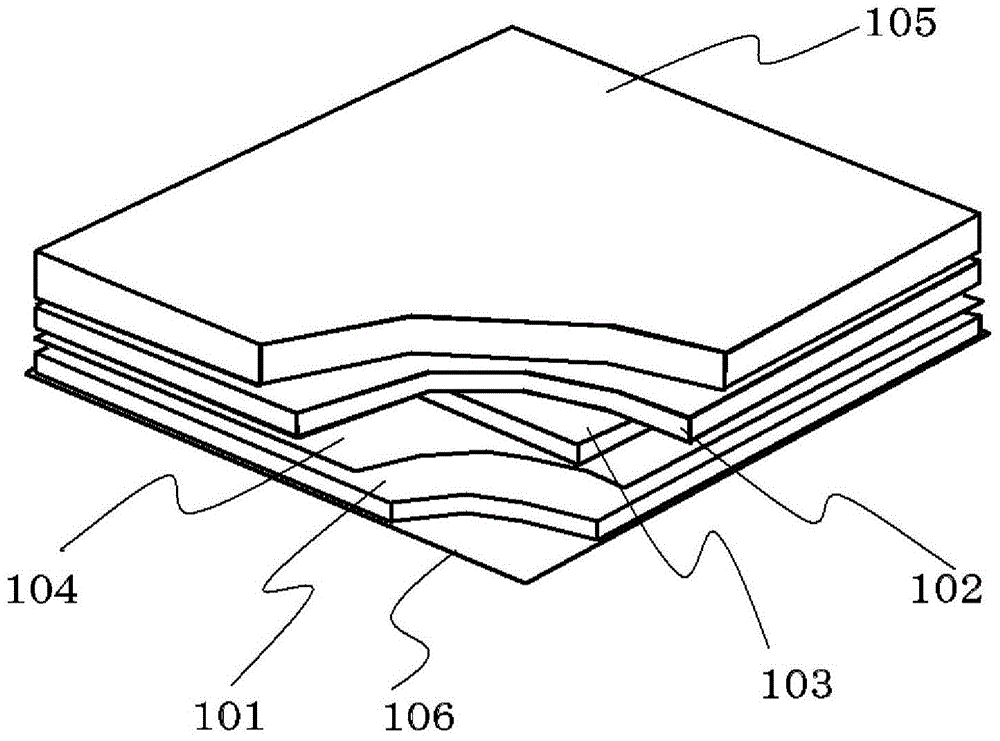
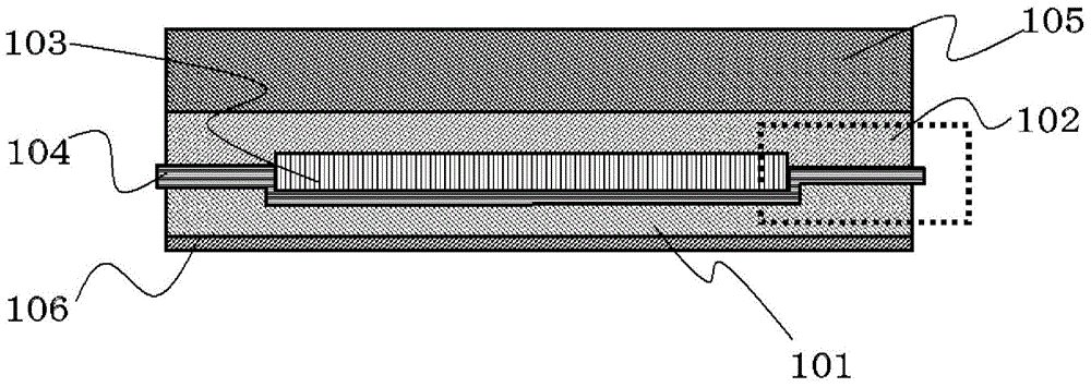
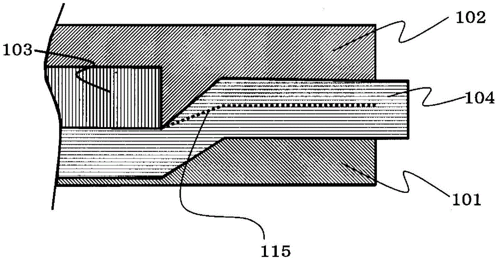
[0030] figure 1 It is a perspective view of a state where a part of the solar cell module of Embodiment 1 is peeled off, Figure 2A is its cross-sectional view, Figure 2B is going to be run by Figure 2A The enlarged cross-sectional view of the part enclosed by the dotted line.
[0031] The solar cell module according to Embodiment 1 includes: a solar cell element 103; an upper sealing portion 102 positioned above the solar cell element 103; a porous body 104 positioned below the solar cell element 103; and a lower sealing portion positioned under the porous body 104. part 101; the uppermost protective member 105 located on the upper part of the upper sealing part 102;
[0032] The solar cell element 103 is sandwiched between the upper sealing part 102 and the lower sealing part 101 . Figure 2B The dotted line in represents the interface 115 between the upper sealing part 102 and the lower sealing part 101 .
[0033] The solar cell element 103 is sandwiched by the shee...
Embodiment approach 2
[0048] In Embodiment 2, the porous body 104 is provided with a portion where the solar cell element 103 is inserted as an opening. For this opening, use Figure 3A , Figure 3B , Figure 4A , Figure 4B Be explained. Items not described are the same as those in Embodiment 1.
[0049] Figure 3A It is a cutaway perspective view of the corner of the solar cell module. Figure 3B It is an exploded view illustrating the relationship between the solar cell element 103 and the porous body 104 . Figure 4A is a cross-sectional view of the solar cell module, Figure 4B By Figure 4A An enlarged cross-sectional view of the part enclosed by the dotted line. Figure 4B The dotted line in is the interface 115 between the sealing material of the upper sealing part 102 and the sealing material of the lower sealing part 101 . The sealing resin enters the porous body 104 .
[0050] like Figure 3B As shown, the porous body 104 has an opening 114 whose size is larger than the size ...
Embodiment 1
[0071] As a sealing material for the upper sealing portion 102 , an ethylene-vinyl acetate copolymer (EVA) sheet having a total light transmittance of 92% (measured with BaseMeter HR-100 by Murakami Color Technology Laboratory Co., Ltd.) was used. As the sealing material of the lower sealing portion 101, rutile-type titanium oxide containing 5 wt% in ethylene-vinyl acetate copolymer and having a total light reflectance of 75% (measured by BaseMeter HR-100 by Murakami Color Technology Research Institute Co., Ltd. Determination) sealing material.
[0072] Next, as the porous body 104 , a polyester spunbond nonwoven fabric that is an organic nonwoven fabric was used.
[0073] The lamination method is to place an EVA sheet with a total light transmittance of 92% as a sealing material of the upper sealing part 102 on the white board tempered glass as the uppermost protective material 5 , and place the solar cell element 103 thereon. Next, as the porous body 104, a polyester spun-b...
PUM
 Abstract
Description
Claims
Application Information
 - R&D
- Intellectual Property
- Life Sciences
- Materials
- Tech Scout
- Unparalleled Data Quality
- Higher Quality Content
- 60% Fewer Hallucinations
Browse by: Latest US Patents, China's latest patents, Technical Efficacy Thesaurus, Application Domain, Technology Topic, Popular Technical Reports.
© 2025 PatSnap. All rights reserved.Legal|Privacy policy|Modern Slavery Act Transparency Statement|Sitemap|About US| Contact US: help@patsnap.com


