Solar battery module
A solar cell and panel technology, applied to photovoltaic modules, photovoltaic module support structures, circuits, etc., can solve the problems of solar cell module power generation efficiency reduction and achieve high reliability
- Summary
- Abstract
- Description
- Claims
- Application Information
AI Technical Summary
Problems solved by technology
Method used
Image
Examples
Embodiment approach 1
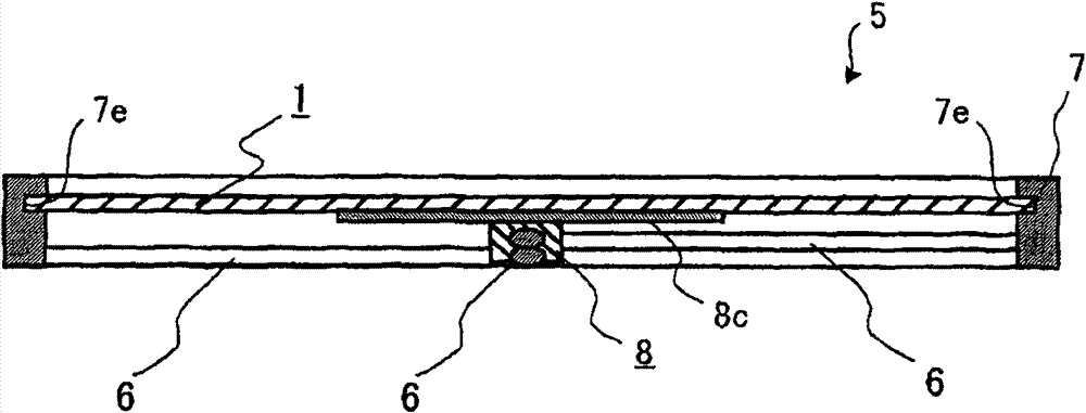
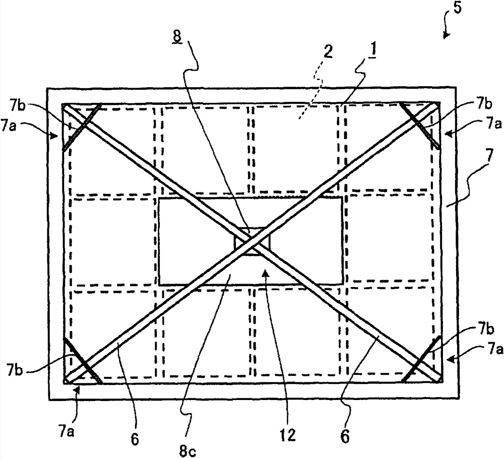
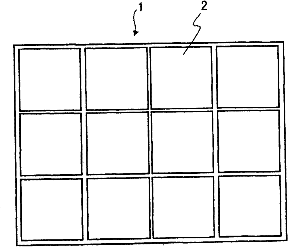
[0052] figure 1 It is a longitudinal sectional view showing Embodiment 1 of the solar cell module of the present invention, figure 2 It is a bottom view of the solar cell module of Embodiment 1, image 3 It is a plan view of the solar cell panel included in the solar cell module of Embodiment 1, Figure 4 It is a partial bottom view showing the junction of the outer frame and the beam of the solar cell module according to Embodiment 1, Figure 5 It is a perspective view showing the support base of the solar cell module of Embodiment 1, Image 6 It is a partial vertical cross-sectional view of a solar cell panel included in the solar cell module according to the first embodiment.
[0053] Such as Figure 1 to Figure 5 As shown, the solar cell module 5 of Embodiment 1 includes a rectangular plate-shaped solar cell panel 1 in which a plurality (12 in Embodiment 1) of rectangular plate-shaped solar cells 2 are arranged at intervals on the same surface. ; an aluminum alloy re...
Embodiment approach 2
[0070] Figure 7 It is a longitudinal sectional view showing Embodiments 2 and 3 of the solar cell module of the present invention, Figure 8 It is a partial longitudinal sectional view of a solar cell panel included in the solar cell module according to the second embodiment.
[0071] Such as Figure 7 as well as Figure 8 As shown, the solar cell module 25 according to Embodiment 2 includes: a rectangular plate-shaped solar cell panel 21 in which a plurality of solar cell cells 2 are arranged; Made of rectangular frame-shaped outer frame 7.
[0072] Additionally, if Figure 8 As shown, in the solar cell panel 21, the solar cell unit 2 (in Figure 8 Only one is shown in the figure, but a plurality of solar battery cells are arranged at intervals on the same surface. 2) It is covered with a flexible resin cell protection member 4 such as EVA. A surface protection member 3 made of plate-shaped tempered glass is bonded to the surface. Furthermore, the back plate 14 is bon...
Embodiment approach 3
[0090] Figure 10 It is a partial vertical cross-sectional view of a solar cell panel included in a solar cell module according to Embodiment 3 of the present invention.
[0091] Such as Figure 10As shown, in the solar cell panel 31 of Embodiment 3, the solar cell 2 is covered with a flexible cell protection member 4, the surface protection member 3 is bonded to the surface, and the back surface is used as the back plate 14. The outer skin plate 18 sandwiches sandwich-structured panels 14 on both sides of a plate-like core 19 . In addition, the structure of the solar cell module 35 of Embodiment 3 is the same as Figure 7 The solar cell modules 25 shown are the same.
[0092] The sandwich panel 14 represented by a honeycomb panel has a very large bending rigidity, and is bonded on the back side of the solar cell panel 31 as a back panel 14, thereby preventing damage caused by the bending deformation of the solar cell unit 2. damaged.
[0093] Especially in the neutral ax...
PUM
 Abstract
Description
Claims
Application Information
 - R&D
- Intellectual Property
- Life Sciences
- Materials
- Tech Scout
- Unparalleled Data Quality
- Higher Quality Content
- 60% Fewer Hallucinations
Browse by: Latest US Patents, China's latest patents, Technical Efficacy Thesaurus, Application Domain, Technology Topic, Popular Technical Reports.
© 2025 PatSnap. All rights reserved.Legal|Privacy policy|Modern Slavery Act Transparency Statement|Sitemap|About US| Contact US: help@patsnap.com


