High pressure pumps for fuel injection systems

A high-pressure pump and housing technology, which is applied in the direction of pumps, multi-cylinder pumps, liquid variable capacity machines, etc., to achieve the effect of time consumption and low cost.

Inactive Publication Date: 2016-12-21
ROBERT BOSCH GMBH
View PDF7 Cites 0 Cited by
  • Summary
  • Abstract
  • Description
  • Claims
  • Application Information

AI Technical Summary

Problems solved by technology

However, this would mean that the other drive components, which fit exactly into the drive shaft, would also have to be replaced, which would eventually lead to a replacement of the pump

Method used


Image

  • High pressure pumps for fuel injection systems
  • High pressure pumps for fuel injection systems

Examples


Embodiment Construction

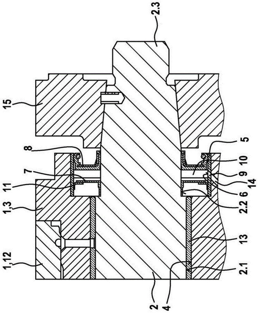
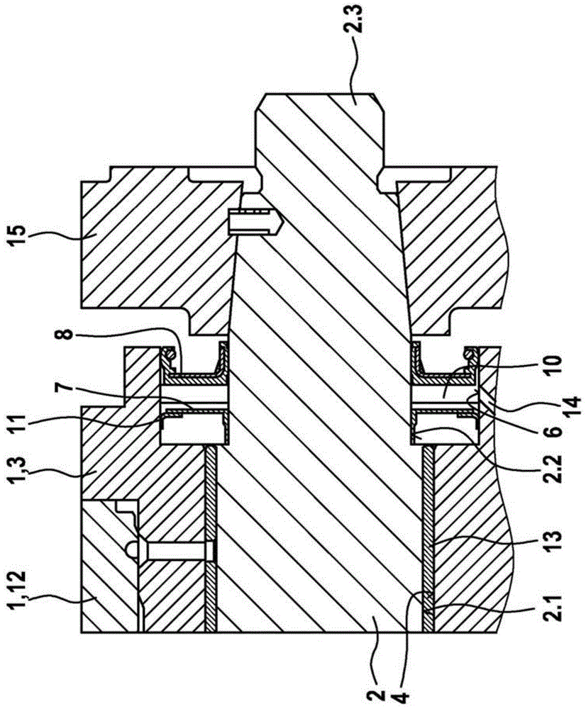
[0022] The high pressure pump of the present invention is figure 1 The preferred embodiment shown in includes a housing 1 with a base body 12 and a flange component 3 which is connected to the base body 12 . A bearing bore 4 designed as a stepped bore for receiving the shaft section 2 . 1 of the drive shaft 2 is formed in the flange component 3 . A plain bearing sleeve 13 for forming a plain bearing is inserted into the inner first section of the bearing bore 4 . The sleeve 5 for forming a running surface for the two shaft sealing rings 7 , 8 is pressed into the other outer section of the bearing bore 4 , which has a larger diameter than the first section. Inner diameter. The larger inner diameter forms a receiving space for the shaft sealing rings 7 , 8 .

[0023] The two shaft sealing rings 7 , 8 arranged at an axial distance relative to each other press against an outer peripheral region 2 . 2 of the shaft section 2 . of the outer diameter. The drive shaft 2 is therefo...


PUM


Abstract

The invention relates to a high-pressure pump for a fuel injection system with a multipart housing (1), in which a drive shaft (2) for driving at least one pump element is rotatably mounted, wherein a part of the casing (1) is a flanged component (3) with a bearing bore (4) for receiving a shaft section (2.1) of said drive shaft (2). According to the invention, the flanged component (3) or a bush (5) inset into said flanged component (3) has an internal circumferential face (6), which forms a bearing surface for at least one shaft seal ring (7, 8), sealing radially outwards, which is connected to the drive shaft (2) for sealing the bearing bore (4).

Description

technical field [0001] The invention relates to a high-pressure pump for a fuel injection system, especially a high-pressure common rail injection system. Background technique [0002] A fuel delivery device for an internal combustion engine is known from laid-open document DE 10 2010 043 365 A1, which has a housing for receiving at least one delivery module and a drive shaft for driving the delivery module. The drive shaft is rotatably mounted in a bearing bore of the housing, wherein the bearing bore also accommodates at least two axially spaced apart seals in the form of shaft seal rings. The shaft sealing ring rests with a sealing contour on a shaft section of the drive shaft, wherein the shaft section serves as a running surface. [0003] When it is necessary to separate two different media from one another, then generally at least two seals including shaft sealing rings are required. If the delivery device is installed on the internal combustion engine with oil lubri...

Claims


Application Information

Patent Timeline
Patent Type & Authority Patents(China)
IPC IPC(8): F04B1/04
CPCF04B1/0448
Inventor F·卢卡雷利
Owner ROBERT BOSCH GMBH
Why Eureka
Try Eureka