
Superimposed composite component

A technology of parts and overlapping surfaces, applied in vehicle parts, synthetic resin layered products, superstructure sub-assemblies, etc., can solve the problems of unstable deformation mode and uneven touch, and achieve structural changes, stable deformation methods, and structural changes. simple effect

Active Publication Date: 2015-02-25
TOYODA IRON WORKS CO LTD
View PDF5 Cites 1 Cited by
  • Summary
  • Abstract
  • Description
  • Claims
  • Application Information

AI Technical Summary

Problems solved by technology

[0007] However, in such conventional superimposed composite parts, only simple cylindrical protrusions are provided, so the deformation method (deflection direction, etc.) when elastically deformed by a pressing load is unstable, and there is a problem that the tactile feeling tends to be uneven.

Method used


Image

  • Superimposed composite component
  • Superimposed composite component
  • Superimposed composite component

Examples


Embodiment

[0114] Below, while referring to the attached Figure 1 Embodiments of the present invention will be described in detail.

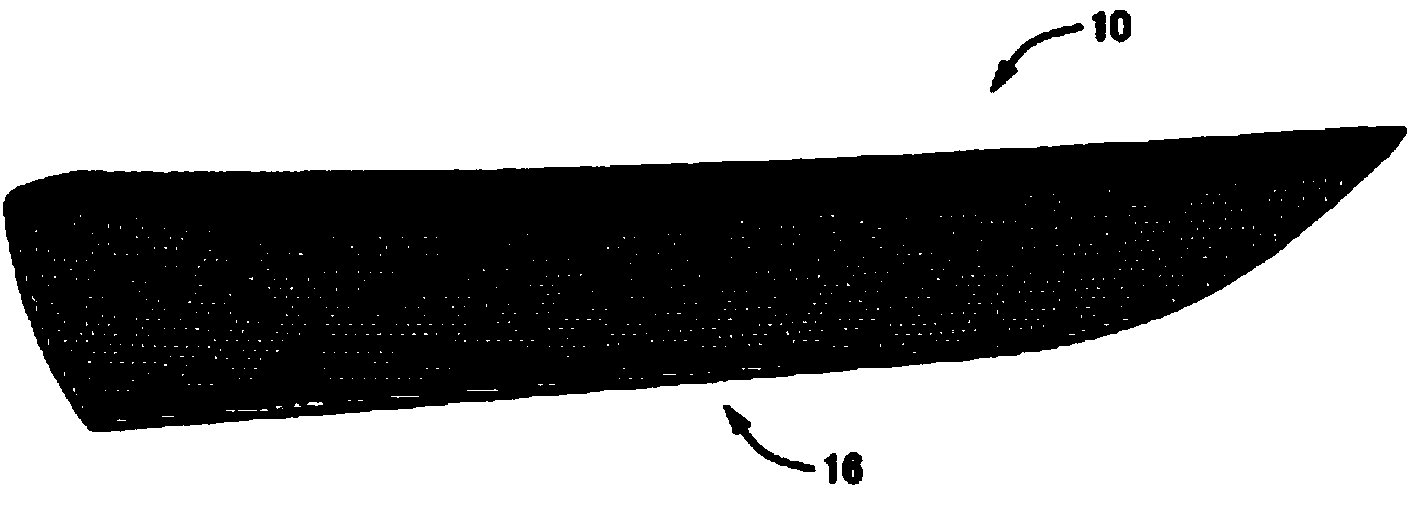
[0115] figure 1 It is a schematic diagram showing the shoulder portion (lower end portion of the window) of the upper end of the door trim 12 for a vehicle having the ornament 10 of the present invention, and is the main view seen from the design surface side of the door on the right side of the vehicle, that is, the interior side. view. figure 2 is a separate representation figure 1 The figure of the decoration 10 of the present invention shows a plurality of tiny protrusions 20 provided on the inside of the surface member 16 in perspective from the design surface side (refer to Image 6 etc.), image 3 It is a figure showing the base material 14 with the surface member 16 of the decorative article 10 removed. in addition, Figure 4 With figure 1 A cross-sectional view of an ornament 10 corresponding to the portion viewed from the arrow IV-IV in ...


PUM


Abstract

The multiple small protrusions 20 have an elongate shape in a planar view and are arranged at such locations as to form the respective sides of each of polygon such that there is formed the lattice pattern formed of the polygon. Each small protrusion 20 having an elongate shape is easily bent and deformed in the direction perpendicular to the longitudinal direction and is hard to bend and deform in the longitudinal direction. Therefore, the deformation manner at the time when each small protrusion 20 is elastically deformed becomes stable, and variations in the feel at the time when the small protrusions 20 are pressed with a finger or a hand are suppressed. The multiple small protrusions 20 that are formed so as to constitute the lattice pattern are arranged such that the longitudinal directions are offset from each other. Therefore, an appropriate stiff feel is obtained because the small protrusions 20 support each other. Therefore, it is possible to obtain a further excellent feel due to a combination of the appropriate stiff feel and the soft feel through elastic deformation of the small protrusions 20.

Description

technical field [0001] The present invention relates to a superimposed composite part, and particularly relates to a technology for further improving the touch of a superposed composite part provided with cushioning properties by elastic deformation of a plurality of protrusions. Background technique [0002] A superimposed composite part having: (a) a first member having a predetermined superimposed surface; and (b) a second member made of elastically deformable resin and having plate-shaped portion, and a plurality of protrusions protruding toward the overlapping surface so as to form a space between it and the overlapping surface are integrally provided on the plate-shaped portion, in a state where the protrusions are in contact with the overlapping surface to overlap (c) The top end of the protrusion is pressed against the overlapping surface to be elastically deformed, thereby imparting cushioning properties to the overlapping composite part. The part described in Pate...

Claims


Application Information

Patent Timeline
Patent Type & Authority Applications(China)
IPC IPC(8): B32B3/30B60R13/02B60N2/75
CPCB60R13/02B32B3/266B32B3/30B32B27/08B32B2307/51B32B2307/536B32B2605/08B32B7/05Y10T428/24149Y10T428/24165B32B2605/003B60R13/0243
Inventor 宫下长武酒井秀彰
Owner TOYODA IRON WORKS CO LTD
Learn More