
Diesel oil/liquefied petroleum gas co-firing system

A technology for liquefied petroleum gas and diesel, which is applied in the charging system, oil supply device, combustion engine, etc., which can solve the problems of high production cost and time-consuming return to the factory for maintenance.

Inactive Publication Date: 2015-02-25
游素月
View PDF6 Cites 1 Cited by
  • Summary
  • Abstract
  • Description
  • Claims
  • Application Information

AI Technical Summary

Problems solved by technology

[0009] However, the electronic diesel / liquefied petroleum gas co-combustion system requires the installation of sophisticated electronically controlled jet nozzles and jet control units, which is not only expensive to manufacture, but requires specialized technicians to perform adjustment operations, so returning to the factory for maintenance is time-consuming

Method used


Image

  • Diesel oil/liquefied petroleum gas co-firing system
  • Diesel oil/liquefied petroleum gas co-firing system
  • Diesel oil/liquefied petroleum gas co-firing system

Examples


Embodiment Construction

[0102] In order to make readers deeply understand the essence of the present invention, in conjunction with the necessary accompanying drawings, the technical content of the present invention is detailed and specifically stated as follows:

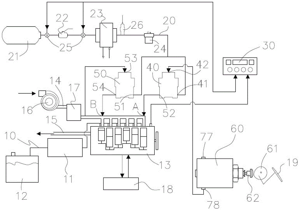
[0103] exist figure 1 In the paper, the specific architecture of a preferred embodiment of the air pressure controlled gas flow type diesel / liquefied petroleum gas mixed combustion energy saving and carbon reduction system is clarified.

[0104] This dual-fuel mixed combustion system includes a diesel delivery pipeline 10 and a liquefied petroleum gas delivery pipeline 20 , and an oil-gas switch 30 is used to switch between different fuels for combustion operation.

[0105] The center of the diesel delivery pipeline 10 is a diesel injection pump 11 , one end of the diesel delivery pipeline 10 is connected to a diesel oil tank 12 , and the other end is communicated with a diesel engine 13 . When the diesel engine 13 is activated, a user de...


PUM


Abstract

The invention provides a diesel oil / liquefied petroleum gas co-firing system. The diesel oil / liquefied petroleum gas co-firing system comprises a diesel oil engine, a diesel oil delivery pipeline and a liquefied petroleum gas delivery pipeline, wherein the diesel oil engine is connected with a gas intake manifold, diesel oil of a diesel oil tank is delivered to the diesel oil engine through the diesel oil delivery pipeline, and the liquefied petroleum gas delivery pipeline is connected with a liquefied petroleum gas storage barrel. The liquefied petroleum gas in the gas storage barrel is delivered to the corresponding positions of the gas intake manifold through two air compression type flow control valves, and the optimum gas injection is obtained, so that the diesel oil / liquefied petroleum gas can be co-fired excellently, and energy conservation and carbon emission reduction are realized.

Description

technical field [0001] The invention relates to the field of diesel / liquefied petroleum gas co-combustion, in particular to a diesel / liquefied petroleum gas co-combustion system which uses a mechanical air pressure closed circuit to control gas flow. Background technique [0002] As we all know, vehicles go deep into our lives and become an indispensable part. While bringing convenient transportation, they will also pollute the surrounding environment and cause adverse effects on human health. Moreover, the soaring international oil price has become a driving force for the development of energy-saving and low-pollution environmentally friendly vehicles, especially the development of gas vehicles, hybrid vehicles and diesel / liquefied petroleum gas (also known as gas) vehicles has been the most successful. [0003] From the analysis of environmental pollution, it is not difficult to find that any engine with a diesel engine operates according to the four strokes of the Diesel ...

Claims


Application Information

Patent Timeline
IPC IPC(8): F02D19/06F02M21/02
CPCY02T10/30
Inventor 游素月
Owner 游素月
Learn More