Transmission for vehicle
A transmission and vehicle technology, which is applied to vehicle components, control devices, transportation and packaging, etc., can solve the problems of increasing the number of sealing components and increasing the size of the transmission, and achieve the effect of preventing dragging resistance and improving operating efficiency
- Summary
- Abstract
- Description
- Claims
- Application Information
AI Technical Summary
Problems solved by technology
Method used
Image

Examples
no. 1 Embodiment approach
[0068] Below, based on Figure 1 to Figure 16 A first embodiment of the present invention will be described.
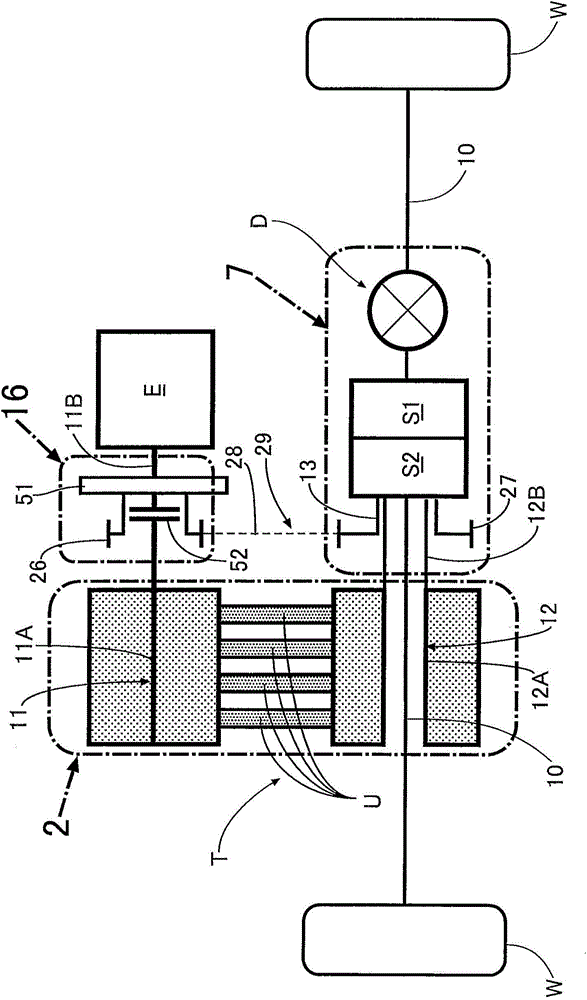
[0069] like figure 1 As shown, the vehicle power transmission device that transmits the driving force of the engine E to the drive wheels W, W through the left and right axles 10, 10 includes: a continuously variable transmission T; a first power transmission switching mechanism S1; a second power transmission switching mechanism S2; and differential D. The first power transmission switching mechanism S1 is capable of switching among a parking position, a reverse position, a neutral position, and a drive position. The second power transmission switching mechanism S2 is switchable between a normal running / engine braking state, an idling stop state, and a failure state.
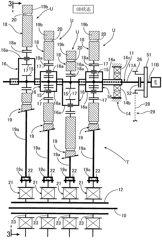
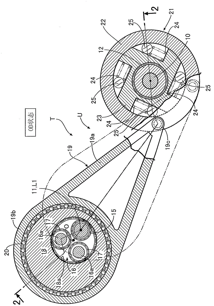
[0070] Next, based on Figure 1 to Figure 7 The structure of the vehicle power transmission device will be described.
[0071] like figure 1 As shown, the input shaft 11 is composed of an input s...
no. 2 Embodiment approach
[0128] Next, based on Figure 17 A second embodiment of the present invention will be described.
[0129] In the first embodiment, the friction surface 54 of the dry clutch 52 is provided on the first side wall 53a of the clutch drum 53, and the pressure plate 56 is arranged on the second side wall 53b side of the clutch drum 53, but in the second embodiment Among them, the positional relationship between the friction surface 54 and the pressure plate 56 is exchanged, the friction surface 54 is provided on the second side wall 53 b of the clutch drum 53 , and the pressure plate 56 is arranged on the first side wall 53 a side of the clutch drum 53 . As a result, the operation shaft 57 that drives the platen 56 is connected to the actuator 59 through the interior of the hollow input shaft main body portion 11A.
[0130] The transmission housing 60 and the extension portion 53d of the clutch drum 53 are sealed by a sealing member 63A, and the gap between the extension portion 53...
no. 3 Embodiment approach
[0132] Next, based on Figure 18 A third embodiment of the present invention will be described.
[0133] In the first and second embodiments, the actuator 59 of the dry clutch 52 is provided on the first chamber 61 side, but in the third embodiment, the actuator 59 is arranged in the second chamber 62 . That is, in the third embodiment, one end of the separation fork 65 pivotally supported by the fulcrum 64 in the middle is connected to the actuator 59, and the other end of the separation fork 65 is brought into contact with the back surface of the pressure plate 56, and the pressure plate 56 passes The splines are supported by the second side wall 53b of the clutch drum 53 so as to be slidable in the axial direction, thereby driving the pressure plate 56 in the axial direction to engage and disengage the dry clutch 52 .
[0134] The transmission housing 60 and the extension portion 53d of the clutch drum 53 are sealed by the seal member 63A, and the gap between the extension...
PUM
 Abstract
Description
Claims
Application Information
 - R&D
- Intellectual Property
- Life Sciences
- Materials
- Tech Scout
- Unparalleled Data Quality
- Higher Quality Content
- 60% Fewer Hallucinations
Browse by: Latest US Patents, China's latest patents, Technical Efficacy Thesaurus, Application Domain, Technology Topic, Popular Technical Reports.
© 2025 PatSnap. All rights reserved.Legal|Privacy policy|Modern Slavery Act Transparency Statement|Sitemap|About US| Contact US: help@patsnap.com