Clamp with quick locking function

A locking clip, fast technology, applied in the direction of clamping, manufacturing tools, supports, etc., can solve the problems of wasting manpower and material resources, time, and cumbersome operation process.

Inactive Publication Date: 2015-02-25
常州恒源钢结构工程有限公司
View PDF0 Cites 0 Cited by
  • Summary
  • Abstract
  • Description
  • Claims
  • Application Information

AI Technical Summary

Problems solved by technology

[0002] Fixtures are often used in the machining process. After the workpiece is placed on the fixture, it is locked by the fixture. After processing, the workpiece needs to be removed. Most of the existing fixtures are cumbersome to operate, which wastes manpower, material resources and time.

Method used


Image

  • Clamp with quick locking function
  • Clamp with quick locking function

Examples


Embodiment Construction

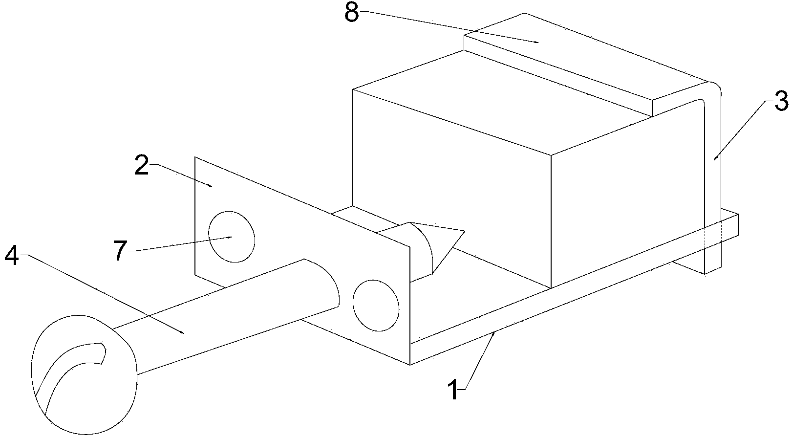
[0015] Depend on figure 1 and figure 2 It can be seen that a fast locking fixture of the present invention includes a bottom plate 1, a left side plate 2, a right side plate 3 and locking screws 4, the bottom plate 1 and the left side plate 2 are integrally structured, and the right side of the bottom plate 1 has A chute 5, the right side of the chute 5 is provided with a positioning bolt 6 threaded with the bottom plate 1, the right side plate 3 passes through the chute 5 from top to bottom, and the left side plate 2 is provided with a plurality of The through hole 7, the locking screw 4 is threadedly matched with the through hole 7, the upper cover 8 is provided on the 3 ends of the right side plate, the upper cover 8 is provided with a fastening bolt 9, and the upper cover 8 is provided with a fastening bolt 9. The cover 8 is integrated with the right side plate 3 , and the upper cover 8 and the right side cover 3 have an arc transition.

[0016] During the work of the p...


PUM


Abstract

The invention relates to a clamp with the quick locking function. The clamp comprises a bottom plate, a left side plate, a right side plate and a locking screw, wherein the bottom plate and the left side plate are of an integrated structure, a sliding groove is formed in the right side of the bottom plate, a positioning bolt is arranged on the right side of the sliding groove, the right side plate penetrates through the sliding groove from top to bottom, through holes are formed in the left side plate, the locking screw is in threaded connection with one through hole, an upper sealing cover is arranged at the upper end of the right side plate, a fastening bolt is arranged on the upper sealing cover, the upper sealing cover and the right side plate are of an integrated structure, and the upper sealing cover is in arc transition with the right side plate. By the adoption of the structure, the clamp can clamp workpieces of different specifications, one workpiece can be clamped by tightening the locking screw, and the workpiece can be clamped more tightly through the fastening bolt on the sealing cover when necessary.

Description

technical field [0001] The invention relates to a clamp, in particular to a fast locking clamp. Background technique [0002] Fixtures are often used in the machining process. After the workpiece is placed on the fixture, it is locked by the fixture. After processing, the workpiece needs to be removed. Most of the existing fixtures are cumbersome to operate, which wastes manpower, material resources and time. Contents of the invention [0003] The purpose of the present invention is to provide a fast locking fixture with simple and reasonable structure and convenient operation. [0004] The technical scheme that realizes the object of the present invention is as follows: [0005] A fast locking fixture, comprising a bottom plate, a left side plate, a right side plate and locking screws, the bottom plate and the left side plate are integrally structured, a chute is provided on the right side of the bottom plate, and a chute is provided on the right side of the chute There...

Claims


Application Information

Patent Timeline
Patent Type & Authority Applications(China)
IPC IPC(8): B23Q3/00
CPCB23Q3/00
Inventor 陈建强
Owner 常州恒源钢结构工程有限公司
Why Eureka
Try Eureka