Gamepad
A gamepad and handle technology, applied in the field of gamepads, can solve the problems of affecting the consistency of operation, affecting the accuracy of operation, and large wear of the trigger button, so as to achieve the effect of facilitating processing and installation, improving operation flexibility, and reducing distance requirements.
- Summary
- Abstract
- Description
- Claims
- Application Information
AI Technical Summary
Problems solved by technology
Method used
Image
Examples
Embodiment 1
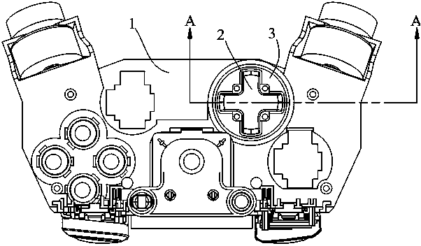
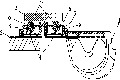
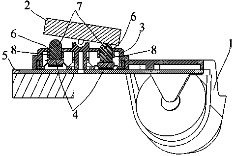
[0017] refer to figure 1 and figure 2 , the game handle of this embodiment includes a handle housing 1, direction keys 2, direction key fixing brackets 3, a plurality of elastic trigger buttons 4 and a trigger circuit board 5, and between the direction keys 2 and each trigger button 4, there are Slide press mechanism. Specifically, each sliding pressing mechanism includes a through hole 6 provided on the upper surface of the direction key fixing bracket 3 and a sliding column 7 slidably arranged in the through hole 6; the through hole 6 is a straight hole, located directly above the trigger button 4, The sliding column 7 is located between the direction key 2 and the corresponding trigger button 4, so that the top end can contact the bottom surface of the direction key 2, and the bottom end can contact the trigger button 4, so as to prevent the direction key 2 from shaking; Any sliding column 7 slides in the through hole 6, so that the sliding column 7 is vertically pressed...
Embodiment 2
[0024] Taking the through hole 6 as a round hole, the guide flange 8 as a cylindrical flange, and the sliding column 7 as a cylinder as an example, the difference from the first embodiment is that in this embodiment, the sliding column 7 is correspondingly provided with a limiting rib 7.1, correspondingly, there is a limit groove 8.1 at the bottom end of the inner surface of the guide flange 8, even if the longitudinal section of the sliding column 7 is in an inverted T shape, correspondingly, the guide slideway formed by the guide flange 8 and the through hole 6 is also It is an inverted T shape, such as Figure 4 As shown, the limiting rib 7.1 is embedded in the limiting groove 8.1, which can limit the sliding of the sliding column 7, limit its sliding stroke, prevent it from falling out, and ensure the reliability of sliding.
[0025] Similarly, the through hole 6, the guide flange 8 and the sliding column 7 may also be in other shapes or structural forms as described in th...
PUM
 Abstract
Description
Claims
Application Information
 - R&D
- Intellectual Property
- Life Sciences
- Materials
- Tech Scout
- Unparalleled Data Quality
- Higher Quality Content
- 60% Fewer Hallucinations
Browse by: Latest US Patents, China's latest patents, Technical Efficacy Thesaurus, Application Domain, Technology Topic, Popular Technical Reports.
© 2025 PatSnap. All rights reserved.Legal|Privacy policy|Modern Slavery Act Transparency Statement|Sitemap|About US| Contact US: help@patsnap.com


