Elevator emergency braking device
An emergency braking and elevator technology, which is applied in transportation, packaging, elevators, etc., can solve the problems of unstable braking force and wear of brake shoes, achieve sufficient braking performance, ensure braking performance, and improve the average friction coefficient Effect
- Summary
- Abstract
- Description
- Claims
- Application Information
AI Technical Summary
Problems solved by technology
Method used
Image

Examples
no. 1 example
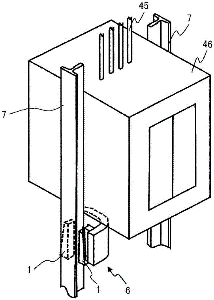
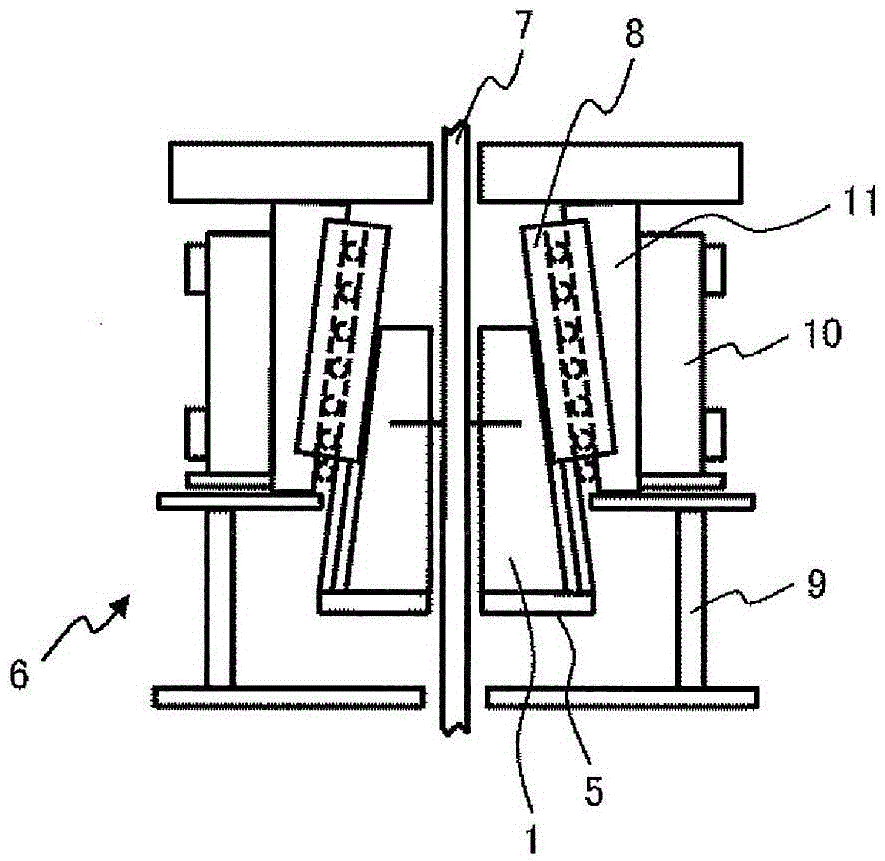
[0055] Figure 4 It is a schematic diagram showing the two-stage emergency brake device according to the first embodiment of the present invention. In the first embodiment, the frame bodies 9 of the respective units are fastened to each other by fastening screws 34, and the figure 2 The illustrated emergency brake device units are stacked vertically to form a two-stage emergency brake device 33 . One end of the upper and lower brake shoes 1A, 1B is provided with a holding member 5 lifted by a driving device (not shown) for driving the emergency braking device 33, and the upper and lower brake shoes 1A, 1B are lifted approximately at the same time, thereby utilizing The wedge action clamps the guide rail 7. Thus, in the first embodiment, since two 1-stage emergency braking devices are provided, each 1-stage emergency braking device has a pair of brake shoes ( 4 brake shoes in total), so the braking force of 8 brake shoes can be obtained in total, which can effectively deal ...
no. 2 example
[0062] Figure 7 It is a schematic diagram showing the multi-stage emergency braking device 35 composed of three-stage emergency braking devices according to the second embodiment of the present invention. In the second embodiment, the three-stage brake shoes are an upper-stage brake shoe 100A, a middle-stage brake shoe 100B, and a lower-stage brake shoe 100C from top to bottom. In the second embodiment, speed energy is absorbed by a high initial friction coefficient, and in order to ensure two consecutive braking actions of the same brake shoe, it is configured as a multi-stage type that switches the actions of each brake shoe. Here, ceramics are used for the upper brake shoe 100A for the same reason as in the first embodiment, and cast iron-based materials are used for the middle brake shoe 100B and the lower brake shoe 100C.
[0063] exist Figure 7 Among them, the characteristic component is the middle brake shoe 100B, which is clamped into the guide rail relative to the...
no. 3 example
[0076] Figure 11 is a schematic diagram showing a third embodiment of the present invention.
[0077] Brake shoe 1E is a mixed material type brake shoe. Its sliding surface is made of metal material M such as cast iron that can obtain a high initial friction coefficient, and ceramic C with wear resistance and heat resistance is embedded in the sliding surface. . In the case of using a mixed material type brake shoe, the entire surface of the brake shoe made of a metal-based material M with a high friction coefficient slides on the guide rail at the moment when braking is started by a single-body brake shoe. Absorb speed energy, and in the subsequent braking, the ceramic C that has not been worn out ensures braking.
[0078] In the case of hybrid material type brake shoes, although it is not easy to meet the conditions of two consecutive braking of the same brake shoe stipulated by foreign standards, it can be applied to elevator specifications with low speed and light load....
PUM
 Abstract
Description
Claims
Application Information
 - R&D
- Intellectual Property
- Life Sciences
- Materials
- Tech Scout
- Unparalleled Data Quality
- Higher Quality Content
- 60% Fewer Hallucinations
Browse by: Latest US Patents, China's latest patents, Technical Efficacy Thesaurus, Application Domain, Technology Topic, Popular Technical Reports.
© 2025 PatSnap. All rights reserved.Legal|Privacy policy|Modern Slavery Act Transparency Statement|Sitemap|About US| Contact US: help@patsnap.com