
System and method for detecting defects of micromotor rotor windings

A rotor winding and defect detection technology, which is applied in the direction of measuring electricity, measuring devices, measuring electrical variables, etc., can solve the problems of small motor winding detection equipment, can not reduce the product rejection rate, find rotor winding faults, etc., to eliminate artificial interference. , the detection speed is fast, the effect of reducing the sampling frequency requirements

Active Publication Date: 2015-02-18
CHONGQING INST OF GREEN & INTELLIGENT TECH CHINESE ACADEMY OF SCI
View PDF6 Cites 11 Cited by
  • Summary
  • Abstract
  • Description
  • Claims
  • Application Information

AI Technical Summary

Problems solved by technology

This detection method completely depends on manually reading the resistance value of the micro-ohmmeter, or manually observing the waveform on the oscilloscope to judge whether the rotor is qualified. Not only the detection efficiency is low, but the accuracy rate is not high. Wrong phenomenon
[0004] And the existing detection equipment is basically a large-scale motor winding fault detector, and the micro-motor winding detection equipment is relatively small
There are some micro-motor comprehensive testers on the market, all of which are used to test the finished motor. It is impossible to find the fault of the rotor winding during the production and assembly stage, and it cannot reduce the product rejection rate.

Method used


Image

  • System and method for detecting defects of micromotor rotor windings
  • System and method for detecting defects of micromotor rotor windings
  • System and method for detecting defects of micromotor rotor windings

Examples


Embodiment

[0058] In conjunction with the examples, the operation process of the detection method of the present invention is described.

[0059] Select a rotor winding with a diameter of 7mm, a winding wire diameter of 0.13mm, a single-phase 18 turns, and a 5-phase (5 commutator segments) for testing. The rotors include normal rotors, single-phase 3-turn short-circuit rotors, broken wire rotors and virtual welded rotors. .

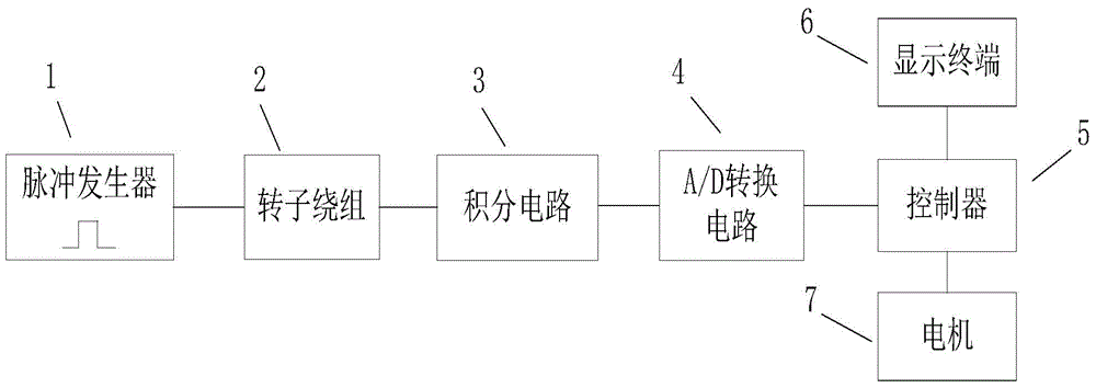
[0060] Operation steps: S1, pulse generator 1 generates a 12V square wave with a duty cycle of 50% and a frequency of 100kHz and loads it on the rotor winding 2;

[0061] S2, the controller 5 controls the motor 7 to rotate 72°;

[0062] S3, the A / D converter 4 collects the voltage of the integrating circuit 3, and transmits it to the controller, and counts once;

[0063] S4. Repeat steps S2-S34 times to complete the sampling of the 5-phase coils of the rotor winding, and the controller performs a data processing program to distinguish the state of the rotor windin...


PUM


Abstract

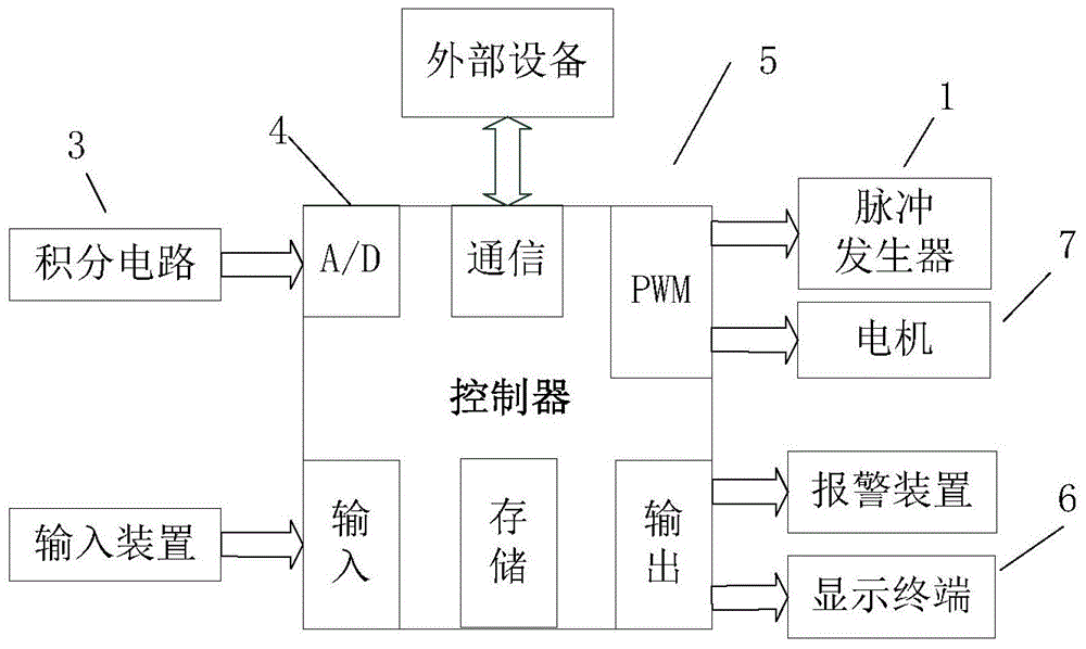
The invention provides a system and method for detecting defects of micromotor rotor windings. According to the system and method, pulse square waves with specified peak values and frequencies are exerted to a tested rotor winding, response signals and standard rotor winding signals are collected, compared and analyzed, and whether the rotor winding has faults and fault modes are judged. The corresponding detection system comprises a pulse generator, a rotor winding, an integral circuit, an A / D switching circuit, a controller, a display terminal and a motor. The pulse generator exerts pulse signals on the rotor winding, and the integral circuit is connected to the two ends of each commutator bar of the rotor winding in parallel; the A / D switching circuit collects voltages at the two ends of an integrating capacitor C in the integral circuit and converts the voltages to digital signals which are transmitted to the controller; the motor is controlled by the controller to drive the rotor winding to rotate to the next set of commutator bars; the controller outputs an operation result to the display terminal. By means of the system and method, the states of the rotor winding can be automatically, quickly and accurately detected, a production line is optimized, and the yield of an assembly line is improved.

Description

technical field [0001] The invention relates to automatic detection technology and belongs to the field of motor detection, in particular to a defect detection system and method for a rotor winding of a micro-motor. Background technique [0002] With the development of society and the advancement of science and technology, micro-motors are more and more widely used in mobile phones, audio-visual products and other fields, and people's performance requirements for micro-motors are becoming more and more stringent, which puts forward higher requirements for motor production testing . [0003] In the process of motor production inspection, rotor winding faults are the main faults, including: disconnection, virtual welding and inter-turn short circuit, and the inter-turn short circuit fault of winding is the most difficult to detect. The existing detection method is to use a micro-ohmmeter to measure the winding resistance, or to add pulses to the winding, and to detect the win...

Claims


Application Information

Patent Timeline
IPC IPC(8): G01R31/06
Inventor 王晓东石明全张鹏井光辉赵迎朱海鹏
Owner CHONGQING INST OF GREEN & INTELLIGENT TECH CHINESE ACADEMY OF SCI
Learn More