
Sliding type loading mechanism applied to automatic pipettor tip loader

A pipette tip and loading mechanism technology, which is applied in the field of loading mechanism and sliding loading mechanism, can solve the problems of low loading efficiency, and achieve the effects of high working efficiency, compact structure, and accurate feeding

Inactive Publication Date: 2015-02-18
李俊
View PDF5 Cites 2 Cited by
  • Summary
  • Abstract
  • Description
  • Claims
  • Application Information

AI Technical Summary

Problems solved by technology

[0004] The technical problem to be solved by the present invention is: for the loading mechanism on the pipette tip automatic loader in the prior art, the whole process of single material feeding, feeding and blanking can only be carried out alternately as the loading unit, and there is a loading efficiency. low problem

Method used


Image

  • Sliding type loading mechanism applied to automatic pipettor tip loader

Examples


Embodiment

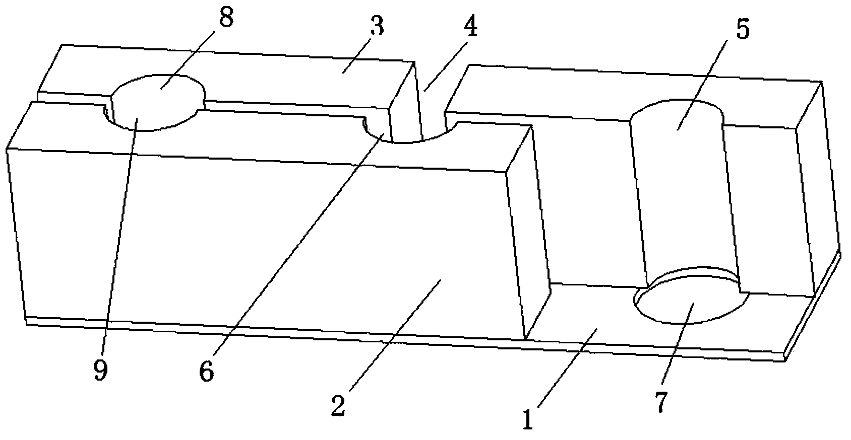
[0028] The pipette tip automatic loader in the present embodiment is the pipette tip automatic loader in the prior art, including frame, vibration plate, direct vibration, movable base, loading tray and loading in the present invention mechanism; its specific installation relationship is:

[0029] Both the vibrating plate and the movable base are installed on the frame, the vibrating plate is connected with the direct vibration, the direct vibration is connected with the loading mechanism, the loading plate is set on the movable base, and the loading plate is located under the loading mechanism.

[0030] The sliding loading mechanism in this embodiment includes a bottom plate 1, a fixed block 3, a slider 2, an incoming material position sensor, a first blanking position sensor and a second blanking position sensor;

[0031] The fixed block 3 is arranged on the bottom plate 1, and the slider 2 is slidably arranged on the bottom plate 1; the fixed block 3 and the slider 2 are ar...


PUM


Abstract

The invention discloses a sliding type loading mechanism applied to an automatic pipettor tip loader, which solves the technical problem of low loading efficiency due to the fact that the whole process of single material feeding, delivery and blanking of a loading mechanism in an automatic pipettor tip loader in the prior art is carried out by loading units alternately. The invention adopts the technical scheme that the sliding type loading mechanism comprises a bottom plate, a stationary block, a slide block, an incoming material position sensor, a first blanking position sensor and a second blanking position sensor, wherein the stationary block is arranged on the bottom plate; the slide block is arranged on the bottom plate in a sliding manner; the stationary block is parallel to the slide block; a feed groove is formed in the stationary block; the incoming material position sensor is arranged above the feed groove in the stationary block; a first blanking groove and a second blanking groove are formed in the stationary block; the first blanking position sensor is arranged above the first blanking groove in the stationary block; and the second blanking position sensor is arranged above the second blanking groove in the stationary block. The mechanism has the advantages that two materials are loaded alternately, gapless acquisition of tips and drippage of the tips are achieved; and the loading efficiency is improved.

Description

technical field [0001] The invention relates to a loading mechanism, more specifically to a sliding loading mechanism applied to a pipette tip automatic loading machine, and belongs to the field of packaging. Background technique [0002] Micropipettes are single-channel micropipettes commonly used in biological and chemical laboratories to pipette liquids with small volumes. Tips are one of the most commonly used parts of pipettes. Because the tips are more precise and easily damaged, the main Relying on manual packing, the existing mechanical packing equipment has problems such as missing and wrong packing, which need to be improved. [0003] In the prior art, the loading mechanism on the pipette tip automatic loader can only take the whole process of feeding, feeding and blanking a single piece of material as the loading unit alternately, which has the problem of low loading efficiency. Contents of the invention [0004] The technical problem to be solved by the presen...

Claims


Application Information

Patent Timeline
IPC IPC(8): B65B35/30
CPCB65B35/30B65B57/14
Inventor 李俊
Owner 李俊
Learn More