Box body type workpiece shot blasting cleaning device for upper mobile material conveying

A shot blasting cleaning and top-mounted technology, which is applied in the direction of the used abrasive processing device, abrasive feeding device, abrasive, etc., can solve the problem that the relative direction of the projectile and the workpiece cannot be adjusted in all directions, and the treatment and cleaning are not complete. Realize automation and other issues to achieve the effect of low possibility of cleaning dead angle, efficient shot blasting treatment, and improved shot blasting efficiency

Inactive Publication Date: 2015-02-18
UNIV OF JINAN
View PDF9 Cites 7 Cited by
  • Summary
  • Abstract
  • Description
  • Claims
  • Application Information

AI Technical Summary

Problems solved by technology

[0003] But the shot blasting machine that current industry is used mainly has the defective of two aspects when carrying out shot blasting cleaning to engine casing: the one, when carrying out shot blasting cleaning to engine casing, need too much manpower labor, can't realize automation, cost Higher, low mechanical efficiency; second, the position of the workpiece in the shot blasting chamber can only be adjusted relatively, and the relative direction of the projectile and the workpiece cannot be adjusted in all directions, so the projectile thrown by the shot blaster can only hit a part of the workpiece The surface, the part that the projectile cannot hit will be treated and cleaned incompletely

Method used


Image

  • Box body type workpiece shot blasting cleaning device for upper mobile material conveying
  • Box body type workpiece shot blasting cleaning device for upper mobile material conveying
  • Box body type workpiece shot blasting cleaning device for upper mobile material conveying

Examples


Embodiment Construction

[0033] The specific implementation manners of the present invention will be described below in conjunction with the accompanying drawings.

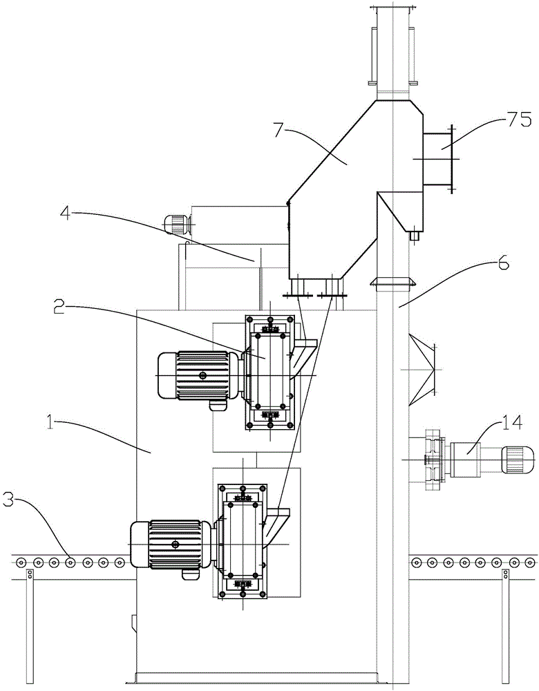
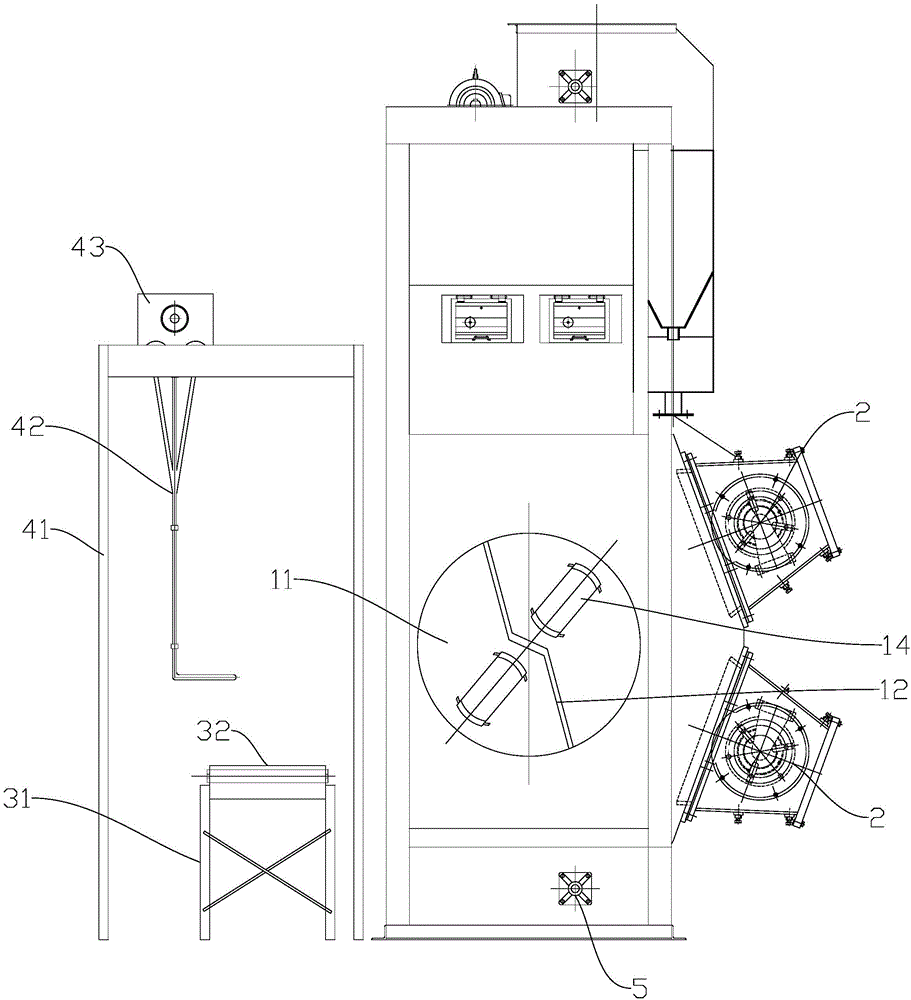
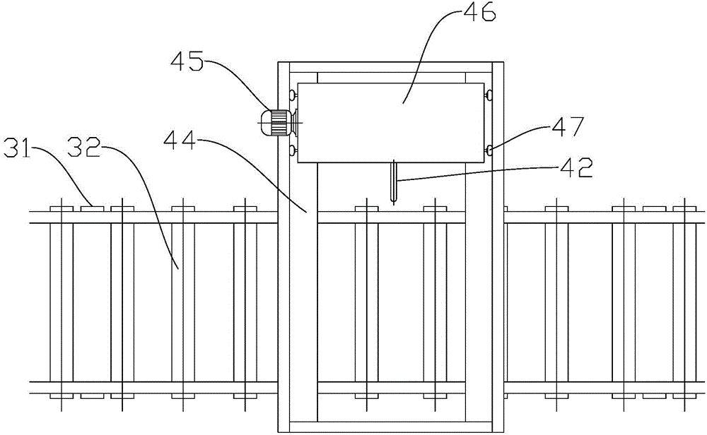
[0034] Such as Figure 1-7 As shown, the shot blasting device includes: a shot blasting chamber 1, a shot blasting device 2, a feeding roller table 3, a feeding manipulator 4, a shot sand circulation system and a shot sand separator 7.

[0035] One side of the shot blasting chamber 1 is provided with an observation port, and the side adjacent to the observation port is provided with a workpiece inlet. In the shot blasting chamber 1, there is a rotary table 11, which is a disc-shaped structure, and Perpendicular to the side where the viewing port is located. Rotary workbench 11 is driven by stepper motor, can realize intermittent rotation, and each rotation angle is 180 °. The rotary table 11 also includes two rotation systems, the two rotation systems are installed on the rotary table 11 along the diameter direction, separated by a part...


PUM


Abstract

The invention discloses a box body type workpiece shot blasting cleaning device for upper mobile material conveying. The box body type workpiece shot blasting cleaning device comprises a shot blasting chamber, shot blasters mounted on the shot blasting chamber, a shot and sand circulating system matched with the shot blasters and a shot and sand separator, wherein a workpiece inlet is formed in one side surface of the shot blasting chamber; the shot blasting cleaning device further comprises material conveying roller ways arranged at one side of the workpiece inlet of the shot blasting chamber and material feeding manipulators; each material feeding manipulator comprises a stander; a rail and a power trolley matched with the rail are arranged on the top of the stander; the direction of the rail is perpendicular to the material conveying roller ways; a lifting hook is perpendicularly mounted on the power trolley; the lower end of the lifting hook is opposite to the workpiece inlet of the shot blasting chamber; a rotary workbench is arranged in the shot blasting chamber; a clamp is arranged on the rotary workbench. The box body type workpiece shot blasting cleaning device is used for achieving multi-orientation and high-efficiency shot blasting treatment of a box body; the possibility of cleaning dead corners is reduced to minimum; the box body type workpiece shot blasting cleaning device is low in overall manufacturing cost, easy to operate, convenient to maintain and good in use effect.

Description

technical field [0001] The invention relates to the technical field of shot blasting, in particular to an upper-mounted mobile feeding box-like workpiece shot blasting device. Background technique [0002] Nowadays, when the surface of the engine case is cleaned and treated in industrial production, shot blasting technology is mostly used for process treatment. The principle is to put the workpiece in a closed container and use a shot blaster to accelerate the projectile. The projectile directly collides with the surface of the workpiece, and the remaining impurities on the surface of the workpiece are cleaned by collision, so as to achieve the purpose of cleaning the surface of the workpiece. Therefore, the workpiece after shot blasting not only increases the surface finish, but also improves the stress state of the workpiece surface, making it in a state of compressive stress, and improving the durability and fatigue strength of the workpiece. [0003] But the shot blasti...

Claims


Application Information

Patent Timeline
Patent Type & Authority Applications(China)
IPC IPC(8): B24C3/02B24C9/00B24C7/00
CPCB24C3/02B24C9/00B24C9/003B24C9/006
Inventor 王守仁李亚东汤以品曹斐高文杨学锋乔阳
Owner UNIV OF JINAN
Why Eureka
Try Eureka