
An Automatic Pressure Regulating Controller Used in Negative Pressure System

A technology of automatic pressure regulation and controller, which is applied in the direction of fluid pressure control, non-electric variable control, electric fluid pressure control, etc. It can solve the problems that remote control cannot be realized and the accuracy is difficult to guarantee, so as to ensure control safety and Accuracy, stable operation, and good stability

Active Publication Date: 2016-08-24
TONGYE TECH DEV
View PDF7 Cites 0 Cited by
  • Summary
  • Abstract
  • Description
  • Claims
  • Application Information

AI Technical Summary

Problems solved by technology

However, the needle valve is used for pressure regulation control, and the outlet ring gap of the needle valve is adjusted manually, so the accuracy is difficult to guarantee, and remote control cannot be realized.

Method used


Image

  • An Automatic Pressure Regulating Controller Used in Negative Pressure System
  • An Automatic Pressure Regulating Controller Used in Negative Pressure System
  • An Automatic Pressure Regulating Controller Used in Negative Pressure System

Examples


Embodiment 1

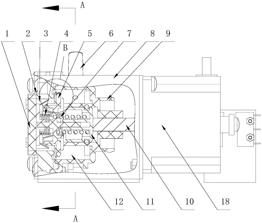
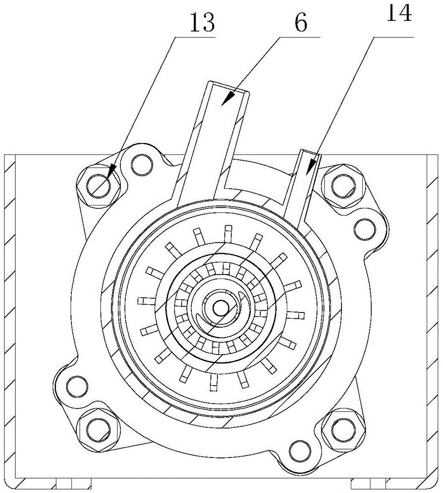
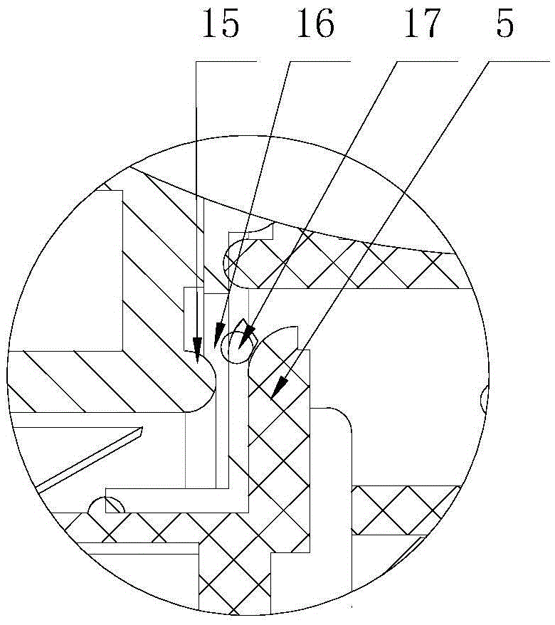
[0030] An automatic pressure regulating controller for a negative pressure system, which mainly consists of a housing 8, an end cover 2, a push rod 10, a negative pressure cover 9, a pressure plate 5, an outer compression spring 4, an inner compression spring 7, and a compression spring Cover 11 and push rod driving mechanism 18 constitute. The fixing screw 13 on the outer circumference of the end cover is fixedly installed on one side of the housing, and the ejector rod driving mechanism is fixedly installed on the other side outside the housing. The above-mentioned negative pressure cover is fixed in the casing, and the negative pressure cover is installed in sealing contact with the inner wall of the end cover to form a pressure regulating chamber 12 . A group of exhaust holes 3 evenly distributed on the circumference are formed on the end cover. A pressure plate is axially installed inside between the negative pressure cover and the end cover, and an external compression ...

Embodiment 2

[0034] The part of the motor shaft of the stepping motor located inside the housing is radially fixed with an inner contact switch plate 22, the outer end of the inner contact switch plate protrudes outside the housing, and the outer end of the contact switch plate is fixed outside the housing Limit switches 21 on both sides of the head. In this embodiment, the contact switch board has two symmetrical outer ends extending out of the housing, and two pairs of limit switches located at the two outer ends are installed on the housing. All the other are the same as in Example 1.

[0035] The working principle of the automatic pressure regulating controller used in the negative pressure system is as follows:

[0036] The negative pressure generated by the negative pressure pump is connected with the negative pressure interface through the rubber hose, so that the negative pressure chamber of the controller is filled with negative pressure. The stepping motor in the figure is a lin...


PUM


Abstract

The invention relates to an automatic pressure regulating controller for a negative pressure system, which mainly consists of a housing, an end cover, a push rod, a negative pressure cover, a pressure plate, an outer pressure spring, an inner pressure spring, a pressure spring sleeve and a push rod The drive mechanism is composed of the end cover fixedly installed on one side of the shell, and the ejector rod drive mechanism is fixed on the other side outside the shell, and a negative pressure cover is fixed in the shell, and an adjustment is formed between the negative pressure cover and the inner wall of the end cover Pressure chamber; a group of exhaust holes is formed on the end cover, the pressure plate is axially installed inside between the negative pressure cover and the end cover, and an external compression spring is axially arranged between the pressure plate and the end cover, and the pressure plate A compression spring sleeve and an internal compression spring are arranged between the ejector rod extending into the negative pressure cover. The coaxial sleeve of the internal compression spring is placed in the compression spring sleeve, and the pressure plate is installed on the elastic support of the internal compression spring and the external compression spring. , the outer end of the ejector rod is connected with the ejector rod driving mechanism, and a negative pressure interface protruding from the outside of the housing is formed on the negative pressure cover. The invention has good repetition accuracy, little external influence, precise control, simple operation and wide application range.

Description

technical field [0001] The invention relates to a pressure system control device, in particular to an automatic pressure regulation controller for a negative pressure system. Background technique [0002] In the fields of medical treatment and chemical industry, it is often necessary to accurately adjust the pressure of the negative pressure system. For example, in the industry, a set of solenoid valves is mostly used for the pressure regulation control of the negative pressure system. By opening and closing different numbers of solenoid valves, the amount of air entering the negative pressure system is controlled to realize the adjustment of the negative pressure value. However, using a group of solenoid valves for pressure regulation control is a discontinuous operation that requires fast response speed of the solenoid valves. Therefore, the cost of the system is high and it is suitable for large-scale vacuum systems. Moreover, the solenoid valve is used to carry out the ...

Claims


Application Information

Patent Timeline
Patent Type & Authority Patents(China)
IPC IPC(8): A61M1/00G05D16/20
CPCA61M1/743G05D16/202
Inventor 殷华李凤林于春泳许广桐翟贵生
Owner TONGYE TECH DEV
Learn More