
Power generation input device and electronic equipment using the power generation input device

A technology for input devices and electronic equipment, applied in circuits, electrical switches, electrical components, etc., and can solve problems such as complex maintenance

Active Publication Date: 2017-03-08
ALPS ALPINE CO LTD
View PDF6 Cites 0 Cited by
  • Summary
  • Abstract
  • Description
  • Claims
  • Application Information

AI Technical Summary

Problems solved by technology

[0005] However, in such a switch installed in a place where it is difficult to route wires, the switch itself needs to have a power supply function necessary for operation.
[0006] The easiest way to make the switch itself have a power supply function is to build a small dry battery inside the switch, but in this case, the battery needs to be replaced regularly, and maintenance is complicated.

Method used


Image

  • Power generation input device and electronic equipment using the power generation input device
  • Power generation input device and electronic equipment using the power generation input device
  • Power generation input device and electronic equipment using the power generation input device

Examples


no. 1 approach

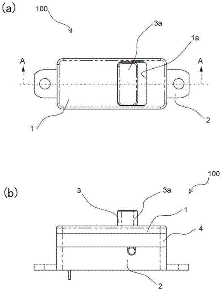
[0057] A power generation input device 100 according to a first embodiment of the present invention will be described with reference to the drawings. figure 1 It is a figure which shows the appearance of the power generation input device 100 of 1st Embodiment, (a) is a top view, (b) is a front view.

[0058] Such as figure 1 (a) and figure 1 As shown in (b), the power generation input device 100 according to the first embodiment of the present invention has a substantially rectangular parallelepiped shape in which the spacer 4 is placed on the upper surface of the housing 2 and the upper cover 1 is placed on the upper surface of the spacer 4 . When the operating handle portion 3a of the operating member 3 protruding from the upper cover 1 is slid and operated, electricity is generated.

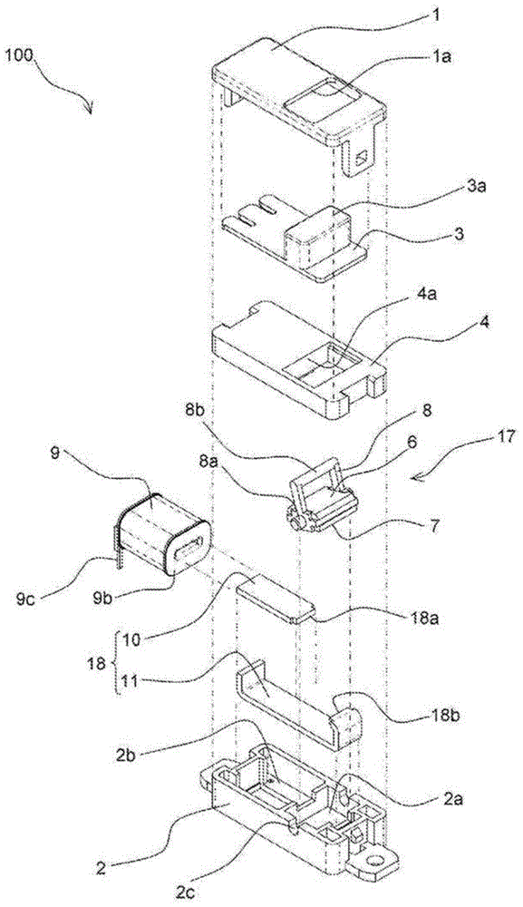
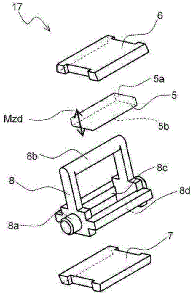
[0059] Next, refer to figure 2 as well as image 3 The component configuration of the power generation input device 100 of the first embodiment will be described. figure 2 It is an e...


PUM


Abstract

Provided is a generating input apparatus such that a large electromotive force can be obtained even when operated slowly by a user. An operating member (3) does not regulate the rotation of a rotating body (17) in the direction from a first posture to a second posture when the rotating body (17) is pushed to rotate in the direction from the first posture to the second posture. Thus, after the rotating body (17) has passed a neutral posture, the rotating body (17) receives magnetic suction force (Fm) in the direction of the second posture due to magnetic suction force between an end face of a first magnetization plate (6) of the rotating body (17) and a second opposite end face (18b) of a magnetic path forming member (18), and to magnetic suction force between an end face of a second magnetization plate (7) of the rotating body (17) and a first opposite end face (18a) of the magnetic path forming member (18), and the rotating body (17) is rotated in the direction of the second posture at high speed. Thus, a magnetic flux (FX) that flows in the magnetic path forming member (18) is rapidly increased, whereby a large electromotive force is produced in a generating coil (9) by electromagnetic induction.

Description

technical field [0001] The present invention relates to a power generation input device capable of generating power by an external operating force, and an electronic device that performs a transmission operation by electromotive force when the power generation input device is operated. Background technique [0002] For example, when additionally installing an operation switch of residential equipment in an existing house or the like, depending on the installation location, it may be difficult or even wire wiring to the additionally installed switch. [0003] In such a case, a switch that operates without wiring wires is required. [0004] A switch that can be operated without wiring can be realized, for example, by transmitting an operation signal when the switch is operated to a control device using wireless or the like, and the control device detects the operation signal to thereby detect the operation state of the switch. In this case, since the installation place of the...

Claims


Application Information

Patent Timeline
Patent Type & Authority Patents(China)
IPC IPC(8): H01H15/16H01H13/64
CPCH01H3/02H01H15/16H01H2003/0266
Inventor 铃木克俊
Owner ALPS ALPINE CO LTD
Learn More