
Rotating shaft and electronic device

A technology of electronic equipment and rotating shaft, which is applied in the direction of pivot connection, electrical digital data processing, instruments, etc., can solve the problems of design cost and production cost waste, and achieve the effect of saving design cost and production cost

Active Publication Date: 2015-02-11
LENOVO (BEIJING) CO LTD
View PDF7 Cites 1 Cited by
  • Summary
  • Abstract
  • Description
  • Claims
  • Application Information

AI Technical Summary

Problems solved by technology

[0007] The embodiment of the present application provides a rotating shaft and an electronic device, which solves the technical problem that in the prior art, flat notebooks that can be flipped and opened 360 degrees and ordinary notebooks need to design and produce different rotating shafts, and there is a waste of design cost and production cost.

Method used


Image

  • Rotating shaft and electronic device
  • Rotating shaft and electronic device
  • Rotating shaft and electronic device

Examples


Embodiment 1

[0047] In Embodiment 1, a rotating shaft is provided, which can connect the first body and the second body of the electronic device, so that the relative rotation between the first body and the second body can be realized. In practical applications, the rotating shaft can be It is applied to electronic devices such as smart phones and tablet notebooks, and will not be listed one by one in this embodiment.

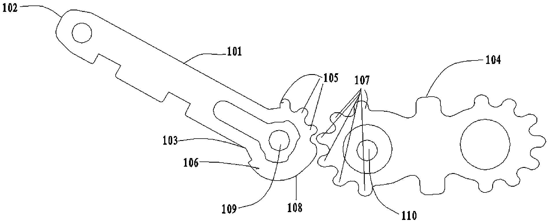
[0048] Please refer to figure 1 , figure 1It is the main structural diagram of the rotating shaft in Embodiment 1 of the present application, and the rotating shaft includes:

[0049] A first bracket 101, wherein the first bracket 101 includes a first fixed end 102 and a first engaging end 103 connected to the first fixed end 102;

[0050] The gear piece 104 is engaged with the first engaging end 103;

[0051] Wherein, the first fixed end 102 is fixed on the first body, and the first engaging end 103 includes:

[0052] M first teeth 105 arranged side by side are used to...

Embodiment 2

[0069] An electronic device is provided in Embodiment 2, please refer to Figure 4 , Figure 4 It is a structural diagram of the front 401 of the electronic device and the back 402 of the electronic device in the embodiment of the present invention, the device includes:

[0070] the first body 403;

[0071] Second body 404;

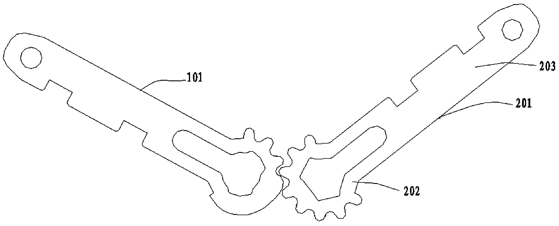
[0072] The rotating shaft 405 as described in the first embodiment;

[0073] The first body 403 is connected with the second body 404 through the rotating shaft 405 .

[0074] The above-mentioned technical solutions in the embodiments of the present application have at least the following technical effects or advantages:

[0075] 1. The embodiment of the present application provides a rotating shaft, M first teeth are arranged side by side on the first meshing end of the first bracket of the rotating shaft, where M is a natural number, and the first teeth are arranged on one side of the M teeth. The limit structure is used to prevent the tooth plate ...


PUM


Abstract

The invention discloses a rotating shaft and an electronic device. The rotating shaft comprises a first support, a tooth piece and a first limiting structure. The first support comprises a first fixed end and a first meshing end; the tooth piece is meshed with the first meshing end; the first fixed end is fixed to a first body; the first meshing end comprises M first teeth which are arranged in parallel and used for being meshed with the tooth piece so as to enable the tooth piece to rotate relative to the first support; the M is a natural number; the first limiting structure is arranged on one sides of the M teeth and is used for preventing the tooth piece from continuing to rotating when second teeth on the tooth piece are in contact with the first limiting structure. The rotating shaft and the electronic device are used for solving the technical problems that in the prior art, according to a tablet computer which can be opened in a 360-degree turn-over mode and a common notebook computer, different rotating shafts need to be designed and produced, and the design cost and the production cost are wasted. The technical effects that the rotating shafts of the tablet computer which can be opened in the 360-degree turn-over mode and the common notebook computer can be generally used, and the design cost and the production cost are saved are achieved.

Description

technical field [0001] The invention relates to the mechanical field, in particular to a rotating shaft and an electronic device. Background technique [0002] Users' personal computing terminals have extended from traditional personal computers to more abundant forms such as tablet computers and smart phones. As two important categories of personal computing terminals, notebooks and tablets are playing an increasingly important role in users' information production and consumption. As users' needs for user experience change, the forms of these two types of products are also constantly merging and evolving. [0003] At present, there is a two-in-one tablet and notebook electronic device with a screen that can be turned back 360 degrees on the market. The device can realize the functions of a tablet. This type of two-in-one tablet notebook electronic device needs to be provided with a rotating shaft that can rotate 360 ​​degrees, so as to realize the angle change between t...

Claims


Application Information

Patent Timeline
IPC IPC(8): F16C11/10G06F1/16
Inventor 夏小松
Owner LENOVO (BEIJING) CO LTD
Learn More