
Flexible insulator for grid component of ion thruster

A technology of ion thrusters and insulators, which is applied in the direction of using plasma, reverse thrust devices, machines/engines, etc., can solve the problem of reducing the variation of the grid spacing of the grid assembly, the inability to effectively release the grid sheet, and the variation of the grid spacing Increase and other problems, to achieve the effect of reducing the failure rate, improving work reliability and facilitating installation

Active Publication Date: 2015-02-11
LANZHOU INST OF PHYSICS CHINESE ACADEMY OF SPACE TECH
View PDF6 Cites 19 Cited by
  • Summary
  • Abstract
  • Description
  • Claims
  • Application Information

AI Technical Summary

Problems solved by technology

[0005] In view of this, the present invention provides a flexible insulator for the grid assembly of the ion thruster. The grid assembly of the ion thruster uses the insulator as the support of the grid sheet, which can effectively release the deformation of the grid sheet due to thermal stress, and reduce the The change of the grid spacing of the grid assembly overcomes the rigid insulator's inability to effectively release the deformation of the grid sheet, which increases the variation of the grid spacing, affects the thrust stability of the ion thruster, and the failure of the ion thruster caused by the short circuit of the grid spacing shortcoming

Method used


Image

  • Flexible insulator for grid component of ion thruster
  • Flexible insulator for grid component of ion thruster

Examples


example

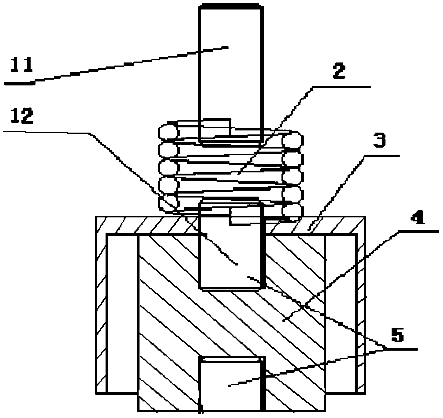
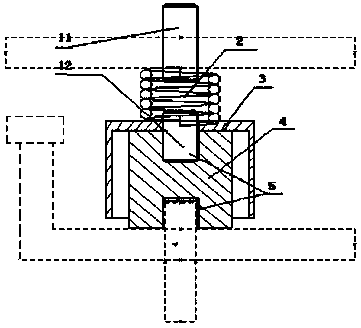
[0034] A flexible insulator is applied to the insulating support of the grid assembly of a 30cm ion thruster (working power 2.5kW-5.0kW). The maximum outline size of the flexible insulator is Ф13mm×16mm, and the specific dimensions are screw 11 and 12: M3×4mm; shape of spring 2: Ф5mm×6mm; shield 3: Ф13mm×8mm; insulating ceramic 4: Ф10mm×9mm; metal thread Hole 5: M3×4mm.

[0035] Use 12 flexible insulators as the insulating support of the 30cm ion thruster grid assembly, the insulators are evenly distributed around the 2 grid sheets, the first screw 11 passes through 12 small holes of Ф3.2mm in the grid sheet (0.5mm thick), Use M3 nuts to connect the grid sheet to the insulator, use 12 M3×4mm bolts to pass through 12 small holes of Ф3.2mm in the grid support ring, and connect with the metal threaded holes, and the grid support ring and the thrust The device is fixedly connected. The grid sheet releases the thermal stress deformation through the spring of the flexible insulato...


PUM


Abstract

The invention discloses a flexible insulator for a grid component of an ion thruster. The insulator comprises a first screw rod, a second screw rod, a spring and insulating ceramic, preferably the insulator further comprises a shielding hood, wherein the shielding hood is of a cavity structure, an opening is formed in one side of the cavity structure, the insulating ceramic is placed in the cavity of the shielding hood, and threaded holes are formed in both end surfaces of the insulating ceramic; the both ends of the spring are respectively connected with the first screw rod and the second screw rod in a welding manner, and the second screw rod penetrates through the bottom surface of the shielding hood and is connected with the threaded hole of one end surface of the insulating ceramic by screw threads, so that the shielding hood and the insulating ceramic are connected together to form the flexible insulator; the threaded hole of the other end surface of the insulating ceramic is used for being in threaded connection with a support ring of a piece of grid through the screw rods, and the first screw rod is used for being in screw joint with the other piece of grid by screw threads. Through the utilization of the grid component of the ion thruster, which is assembled by the flexible insulator, the changes of the spacing between the two grid pieces of the grid component can be effectively reduced, the spacing and the insulation of the two grid pieces are ensured, and the reliability of the ion thruster and the stability of the thrust are ensured.

Description

technical field [0001] The invention relates to the design and manufacture technology of an ion thruster, in particular to a flexible insulator used for a grid assembly of an ion thruster. Background technique [0002] The grid assembly of the ion thruster is composed of two grids connected by insulating supports. For medium-power and high-power (above 2kW) ion thrusters, due to the large beam current drawn by the grid assembly, the temperature difference between the grid sheets is also large. Higher, the deformation of the grid sheet due to thermal stress is also large, which makes the distance between the two grids of the grid assembly (usually about 1mm) decrease, which causes the thrust of the ion thruster to change. When the deformation is severe, it may even cause a short circuit between the grids, resulting in the failure of the ion thruster. [0003] At present, the insulating support used in the grid components of domestic ion thrusters is a rigid insulator, which ...

Claims


Application Information

Patent Timeline
Patent Type & Authority Applications(China)
IPC IPC(8): F03H1/00
CPCF03H1/00
Inventor 郑茂繁张天平唐福俊马林王亮黄永杰
Owner LANZHOU INST OF PHYSICS CHINESE ACADEMY OF SPACE TECH
Learn More