
Autonomous and automatic landing method and system

An automatic landing and runway technology, applied in the direction of automatic control, control start method, aircraft lander, etc., can solve the problem of not being able to guide the aircraft

Active Publication Date: 2015-02-11
AIRBUS OPERATIONS GMBH
View PDF6 Cites 25 Cited by
  • Summary
  • Abstract
  • Description
  • Claims
  • Application Information

AI Technical Summary

Problems solved by technology

However, this system only works when the aircraft is a few meters above the ground and makes it impossible to guide the aircraft during the entire final approach phase, ie during the last approximately 10 kilometers

Method used


Image

  • Autonomous and automatic landing method and system
  • Autonomous and automatic landing method and system
  • Autonomous and automatic landing method and system

Examples


Embodiment Construction

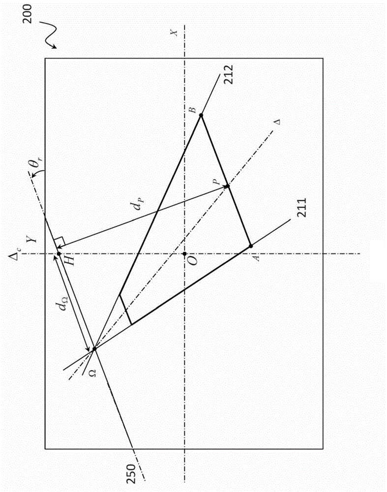
[0053] In the following, an automatic landing system using images captured by at least one onboard camera on board the aircraft will be considered. The term "autolanding system" is understood hereinafter to mean a system enabling an aircraft to land on a landing runway without action by the pilot (autolanding system) or a system assisting the pilot during landing (assisted landing system). In particular, the pilot can at any time correct the commands generated by the autoland system on the basis of visual indications.

[0054] The automatic landing system according to the invention makes it possible to guide or assist the pilot throughout the entire length of the final approach. The automatic landing system is operable as soon as the landing runway has been identified, for example by means of image processing (conventional landing on an airport runway), or indeed when the landing runway is specified by the pilot, especially in the case of an emergency landing on a temporary ru...


PUM


Abstract

A system and method are disclosed for automatic landing of an aircraft on a landing runway, including an on-board video camera intended to take images of the ground, image processor to extract from these images visual features of the landing runway, guidance system determining guidance commands of the aircraft to bring it into a nominal approach plane and to align it with the axis of the landing runway, from the respective positions of the visual features of the landing runway, in at least one of the images, where the guidance commands are supplied to a flight control computer.

Description

technical field [0001] The present invention relates generally to the field of aviation, and more particularly to the field of automatic landing systems. Background technique [0002] The landing phase is a critical phase in the flight of an aircraft because most incidents and accidents occur during this phase. To facilitate the task of the pilot, many automatic landing systems have been proposed. In particular, ILS (Instrument Landing Systems) fitted to high-capacity passenger aircraft are known and ground infrastructures for which exist at international airports. In some European airports MLS (Microwave Landing System) is also available. These systems use radio or microwave signals to guide the aircraft during the approach phase of the aircraft not only in a transverse direction with respect to the axis of the runway, but also in a vertical direction with respect to the glideslope. However, these systems have the disadvantage of not being available in all airports, nota...

Claims


Application Information

Patent Timeline
Patent Type & Authority Applications(China)
IPC IPC(8): B64D45/04
CPCB64C13/16G01S13/913G05D1/101G08G5/025G05D1/0676
Inventor 吉扬·皮约维克托·吉贝尔法比安·佩林
Owner AIRBUS OPERATIONS GMBH
Learn More