
Multi-layer optical coating structure having an antibacterial coating layer

A technology of antibacterial coating and anti-reflection coating, applied in the direction of coating, optics, optical components, etc.

Active Publication Date: 2015-02-11
SAMSUNG DISPLAY CO LTD +1
View PDF5 Cites 40 Cited by
  • Summary
  • Abstract
  • Description
  • Claims
  • Application Information

AI Technical Summary

Problems solved by technology

Anti-reflective coating covers the substrate
Base coat over anti-reflective coating

Method used


Image

  • Multi-layer optical coating structure having an antibacterial coating layer
  • Multi-layer optical coating structure having an antibacterial coating layer
  • Multi-layer optical coating structure having an antibacterial coating layer

Examples


Embodiment Construction

[0015] Exemplary embodiments will now be described more fully hereinafter with reference to the accompanying drawings; however, these embodiments may be embodied in different forms and should not be construed as limited to the embodiments set forth herein. In the drawing figures, the dimensions of layers and regions may be exaggerated for clarity of illustration. It will also be understood that when a layer or element is referred to as being "on" another layer or substrate, it can be directly on the other layer or substrate, or intervening layers may also be present. In contrast, when an element is referred to as being “directly on,” “directly connected to” or “directly coupled to” another element or layer, there are no intervening elements or layers present. Further, it will be understood that when a layer is referred to as being "under" another layer, it can be directly under, and one or more intervening layers may also be present. In addition, it will be understood that wh...


PUM

PropertyMeasurementUnit
refractive indexaaaaaaaaaa

Abstract

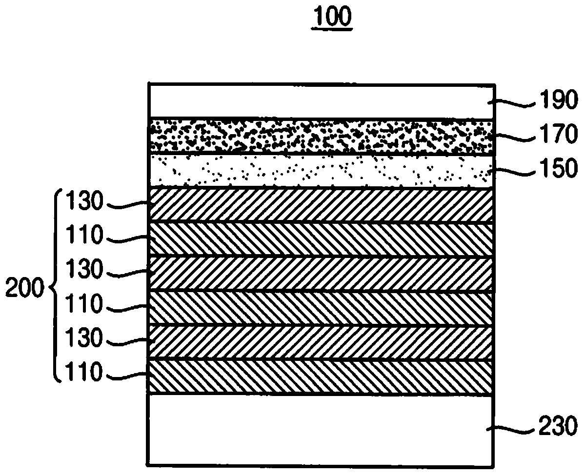
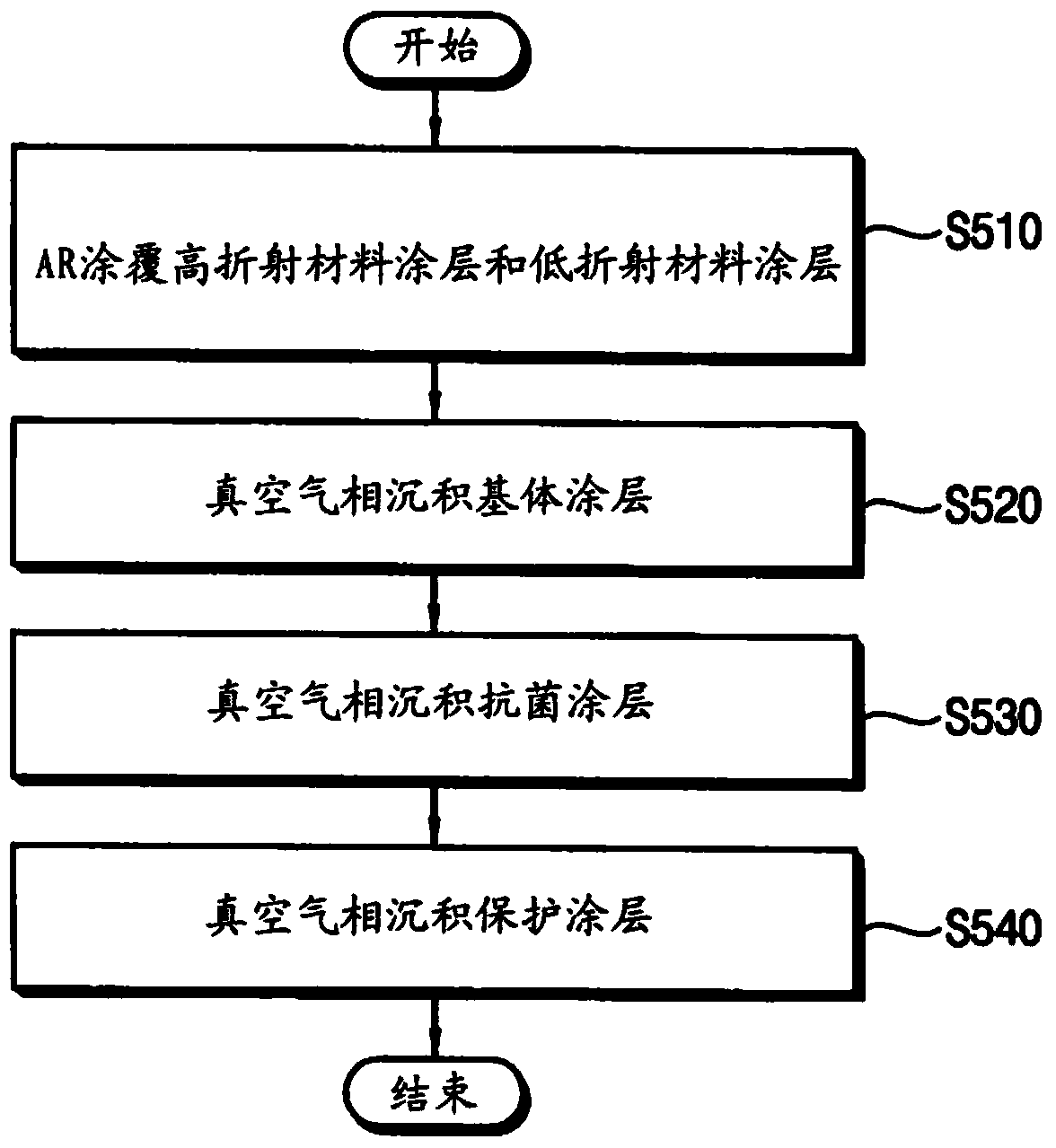
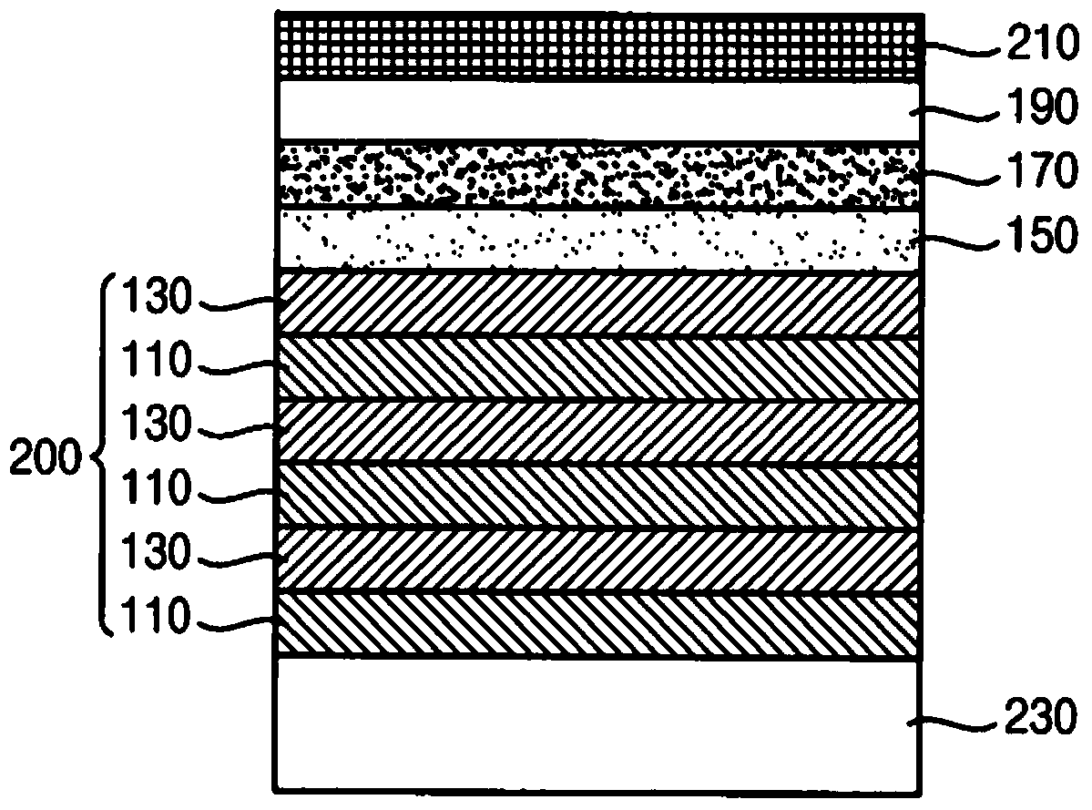
An optical coating structure includes a substrate, an anti-reflective coating layer, a base coating layer, an antibacterial coating layer, and a protective coating layer. The anti-reflective coating layer is disposed on the substrate. The anti-reflective coating layer covers the substrate. The base coating layer covers the anti-reflective coating layer. The antibacterial coating layer is disposed on the base coating layer, and the antibacterial coating layer is an interlayer. The protective coating layer covers the antibacterial coating layer. A super-hydrophobic coating layer or an anti-fingerprint coating layer may cover the protective coating layer.

Description

technical field [0001] Embodiments of the inventive concept relate to optical coating structures. More particularly, embodiments of the inventive concepts relate to optical coatings having antimicrobial coating interlayers. Background technique [0002] Various portable devices having a touch screen panel are used in such a manner that a user's finger touches the touch screen panel countless times. Therefore, the touch screen panel may be contaminated with bacteria or viruses from the user's fingers or external pollutants. In order to prevent penetration of bacteria, viruses, or external pollutants, the touch screen panel may include an antibacterial layer disposed on the touch screen panel. Contents of the invention [0003] According to one aspect of the present disclosure, an optical coating structure includes a substrate, an antireflective coating, a base coating, an antimicrobial coating, and a protective coating. An antireflective coating is disposed on the substr...

Claims


Application Information

Patent Timeline
Patent Type & Authority Applications(China)
IPC IPC(8): B32B9/04B32B27/00B32B17/00B32B33/00C03C17/34C23C14/22C23C16/44
CPCC03C2217/76C03C17/34C03C2217/732C03C17/3417C03C17/42C03C2217/734G02B1/115G02B1/10G06F3/041
Inventor 李祥旭河忠秀曺钟甲赵进镐申度铉
Owner SAMSUNG DISPLAY CO LTD
Learn More