Cylinder body clamping mechanism

A clamping mechanism and cylinder technology, applied in the field of machinery, can solve the problems of time-consuming, labor-intensive, troublesome operation, etc., and achieve the effect of easy industrial production, simple structure and reasonable design

Inactive Publication Date: 2015-02-11
JIANGSU SAIDELI PHARMA MACHINE
View PDF6 Cites 4 Cited by
  • Summary
  • Abstract
  • Description
  • Claims
  • Application Information

AI Technical Summary

Problems solved by technology

[0003] The purpose of the present invention is to overcome the above disadvantages and provide a cylinder clamping mechanism with simple structure and reliability, which can solve the problems of troublesome operation, time-consuming and labor-intensive

Method used


Image

  • Cylinder body clamping mechanism
  • Cylinder body clamping mechanism
  • Cylinder body clamping mechanism

Examples


Embodiment Construction

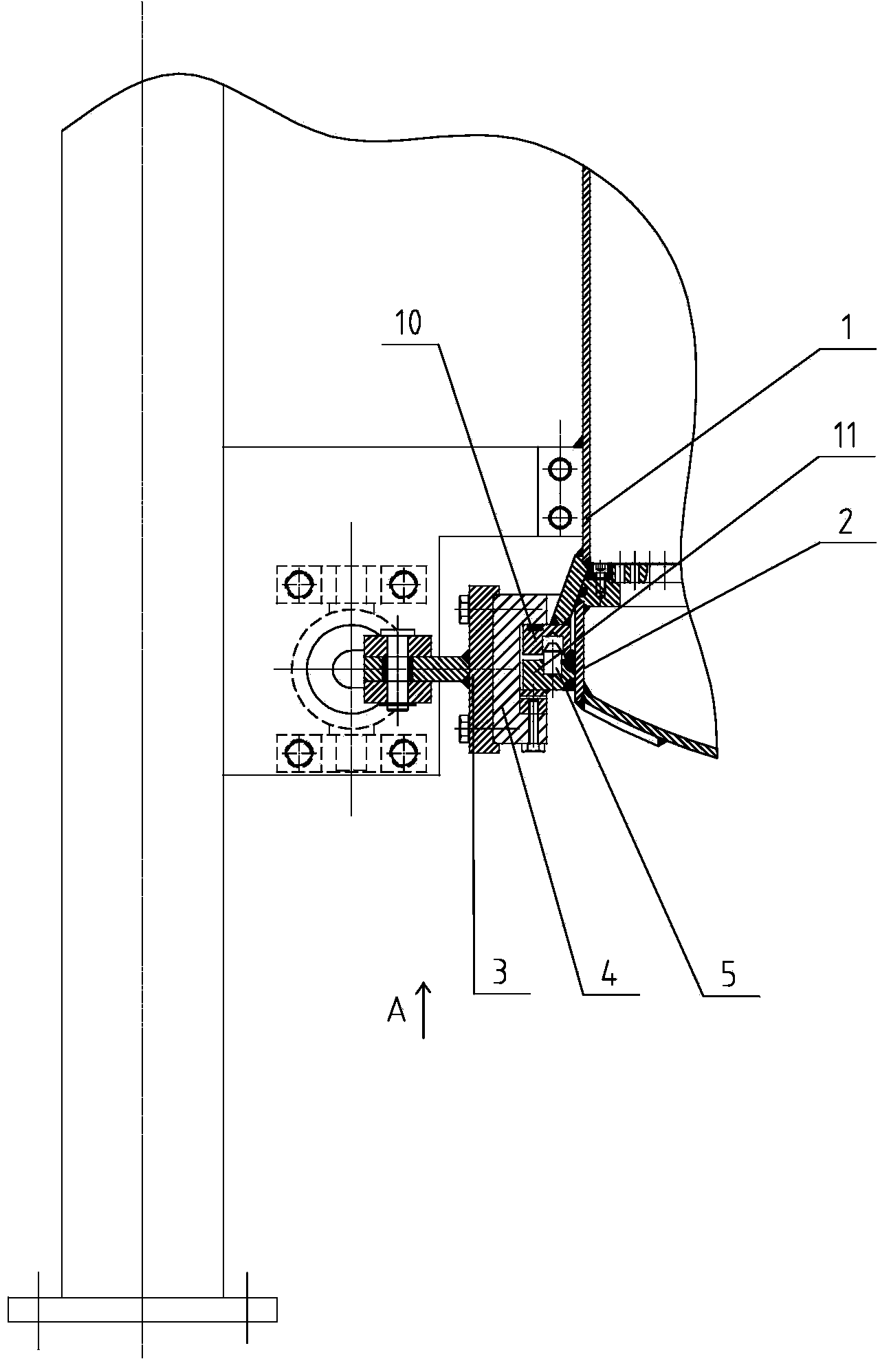
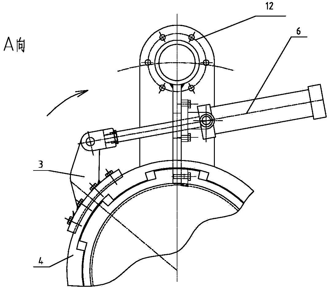
[0015] Such as Figure 1-6 As shown, a cylinder clamping mechanism includes an upper cylinder 1, a lower cylinder 2, a connecting rod 3, a clamping ring 4, an oil cylinder 6, a first flange 10, a second flange 11 and a support plate 12 ;

[0016] The upper cylinder 1 is fixed with a support plate 12, the lower end of the upper cylinder 1 is provided with a first flange 10, and the lower cylinder 2 is provided with a second flange 11; the first flange 10 and the second flange The outer ring of 11 is provided with a clamping ring 4, and the outside of the clamping ring 4 is provided with a connecting rod 3 connected with the piston rod of the oil cylinder 6; the oil cylinder 6 is fixed on the support plate 12.

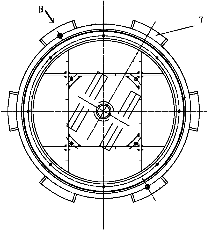
[0017] The second flange 11 is provided with several locking blocks 7 , and each locking block 7 is correspondingly fixed with a first wedge-shaped block 8 ; the second flange 11 is also provided with a guide pin 5 .

[0018] The clamping ring 4 is connected with the s...


PUM


Abstract

The invention relates to a cylinder body clamping mechanism belonging to the technical field of machinery. The cylinder body clamping mechanism comprises an upper cylinder body and a lower cylinder body, wherein a support plate is fixedly arranged on the upper cylinder body, a first flange is arranged at the lower end of the upper cylinder body, and a second flange is arranged on the lower cylinder body; a clamping ring is arranged at the outer ring of the first flange and the second flange, and a connecting rod connected with a piston rod of an oil cylinder is arranged on the outer side of the clamping ring; the oil cylinder is fixed on the support plate. The cylinder body clamping mechanism overcomes the problem of wasting time and labor because locking bolts or locking buckles need to be dismantled one by one when an existing two-in-one or three-in-one filter is cleaned, and the novel cylinder body clamping mechanism provided by the invention is simple in structure and reasonable in design, and easily realizes industrialized production.

Description

technical field [0001] The invention relates to a cylinder clamping mechanism, in particular to a cylinder clamping mechanism for two-in-one and three-in-one filters, and belongs to the field of mechanical technology. Background technique [0002] Two-in-one (filtering, washing) and three-in-one (filtering, washing, drying) filters need to be cleaned after separation in the tank or the residual filter cake on the filter plate during use. In order to facilitate the cleaning operation, the general tank body is designed as a split type, which is fixed by several bolts or locking buckles. During operation, the locking bolts or locking buckles need to be removed one by one, which is time-consuming and laborious. Contents of the invention [0003] The object of the present invention is to overcome the above disadvantages and provide a cylinder clamping mechanism with simple structure and reliability, which can solve the problems of cumbersome operation, time-consuming and labor-...

Claims


Application Information

Patent Timeline
Patent Type & Authority Applications(China)
IPC IPC(8): B01D35/00B01D46/00
CPCB01D35/00B01D46/001
Inventor 顾根生许关红高锐陈洪
Owner JIANGSU SAIDELI PHARMA MACHINE
Why Eureka
Try Eureka