Objective lens and optical pickup device
A technology for an optical pickup device and an objective lens, which can be applied to recording/reproducing by optical methods, systems characterized by a carrier structure, data recording, etc., and can solve problems such as increased cost and unfavorable miniaturization.
- Summary
- Abstract
- Description
- Claims
- Application Information
AI Technical Summary
Problems solved by technology
Method used
Image
Examples
Embodiment 1
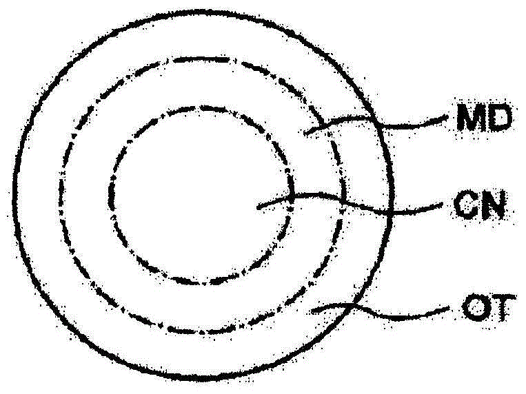
[0334]Tables 1A and 1B show the lens data of Example 1. The objective lens of Example 1 is a plastic single-lens lens, the steps of the first and third basic structures face the direction opposite to the optical axis, and the steps of the second and fourth basic structures face the direction of the optical axis. In addition, in the first optical path difference imparting structure of Example 1, the second base structure of the blazed diffraction structure of (2 / 1 / 1) is superimposed on the second base structure of (1 / 1) in the entire central region. / 1) The optical path difference imparting structure of the first basic structure of the blazed diffraction structure. The second optical path difference imparting structure is a (1 / 1 / 1) blazed type superimposed on the fourth base structure which is a (2 / 1 / 1) blazed type diffractive structure in the entire middle region The optical path difference imparting structure of the third basic structure of the diffractive structure. In add...
Embodiment 2
[0353] Tables 2A and 2B show the lens data of Example 2. The objective lens of Example 2 is a plastic single-lens lens, the steps of the first basic structure and the third basic structure face the direction opposite to the optical axis, and the steps of the second basic structure and the fourth basic structure face the direction of the optical axis. In addition, in the first optical path difference imparting structure of Example 2, the second basic structure of the blazed diffraction structure of (2 / 1 / 1) is superimposed on the second base structure of (1 / 1) in the entire area of the central region. / 1) The optical path difference imparting structure of the first basic structure of the blazed diffraction structure. The second optical path difference imparting structure is a (1 / 1 / 1) blazed type superimposed on the fourth base structure which is a (2 / 1 / 1) blazed type diffractive structure in the entire middle region The optical path difference imparting structure of the third...
Embodiment 3
[0371] Tables 3A and 3B show the lens data of Example 3. The objective lens of Example 3 is a plastic single-lens lens, and the steps of the first and third basic structures face the direction opposite to the optical axis, and the steps of the second and fourth basic structures face the direction of the optical axis. In addition, in the first optical path difference imparting structure of Example 3, the second base structure of the blazed diffraction structure of (2 / 1 / 1) is superimposed on the second basic structure of (1 / 1) in the entire central region. / 1) The optical path difference imparting structure of the first basic structure of the blazed diffraction structure. The second optical path difference imparting structure is a (1 / 1 / 1) blazed type superimposed on the fourth base structure which is a (2 / 1 / 1) blazed type diffractive structure in the entire middle region The optical path difference imparting structure of the third basic structure of the diffractive structure. ...
PUM
| Property | Measurement | Unit |
|---|---|---|
| thickness | aaaaa | aaaaa |
| thickness | aaaaa | aaaaa |
| thickness | aaaaa | aaaaa |
Abstract
Description
Claims
Application Information
 - R&D
- Intellectual Property
- Life Sciences
- Materials
- Tech Scout
- Unparalleled Data Quality
- Higher Quality Content
- 60% Fewer Hallucinations
Browse by: Latest US Patents, China's latest patents, Technical Efficacy Thesaurus, Application Domain, Technology Topic, Popular Technical Reports.
© 2025 PatSnap. All rights reserved.Legal|Privacy policy|Modern Slavery Act Transparency Statement|Sitemap|About US| Contact US: help@patsnap.com


