Drawable socket

A plug-in and board-drawing technology, which is applied in the direction of electrical components, bases/shells, coupling devices, etc., can solve problems such as waste of sockets, and achieve the effects of reducing safety hazards, increasing the use area, and ingenious structure

Inactive Publication Date: 2015-02-04
CHIZHOU YICHUANG ELECTRONICS TECH
View PDF0 Cites 1 Cited by
  • Summary
  • Abstract
  • Description
  • Claims
  • Application Information

AI Technical Summary

Problems solved by technology

[0003] The technical problem to be solved by the present invention is to provide a pullable plug-in strip to solve the problem of wasting existing sockets

Method used


Image

  • Drawable socket
  • Drawable socket
  • Drawable socket

Examples


Embodiment Construction

[0024] In the following, numerous specific details are set forth in order to provide a thorough understanding of the concepts underlying the described embodiments. It will be apparent, however, to one skilled in the art that the described embodiments may be practiced without some or all of these specific details. In other instances, well known processing steps have not been described in detail.

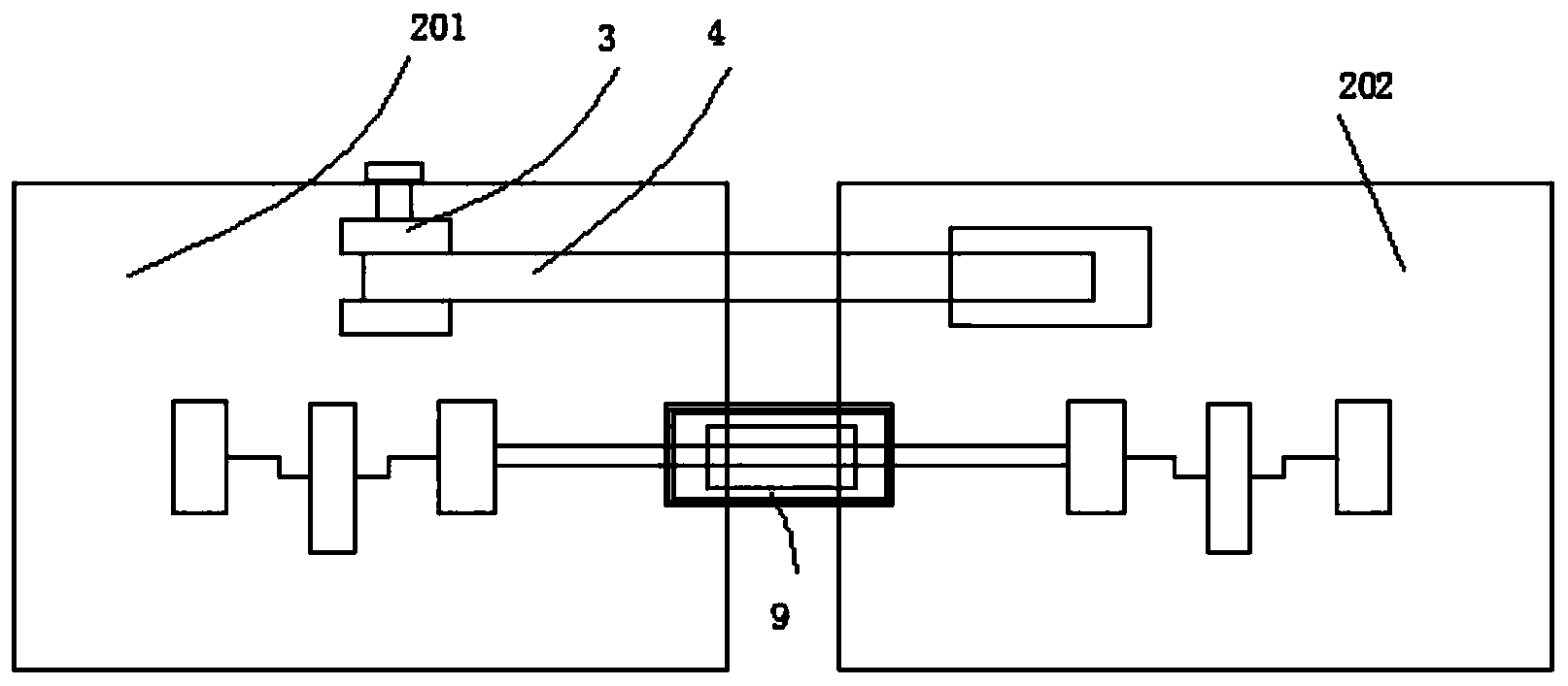
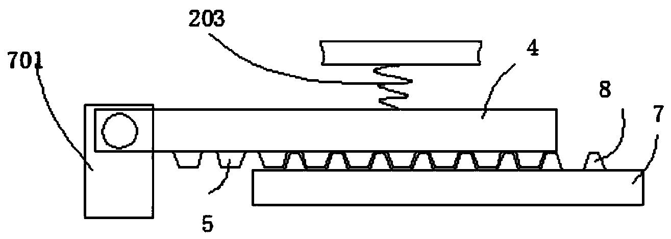
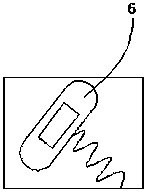
[0025] Such as figure 1 , figure 2 , image 3 , Figure 4 As shown, it includes electric wire 1, including plug-in row 2, pumping board seat 3, pumping board 4, first positioning tooth 5, knob 6, positioning plate 7, second positioning tooth 8, spring tube 9, and the plug-in row 2 Including the first plug-in row 201 and the second plug-in row 202, the pumping board seat 3 is located at the inner bottom of the first plug-in row 201, the two are glued together, the pumping board 4 is located inside the pumping board seat 3, the two The first positioning tooth 5 is located at the b...


PUM


Abstract

The invention discloses a drawable socket, which includes an electric wire, and is characterized by including a socket body, a pulling plate seat, a pulling plate, first positioning teeth, a rotary knob, positioning plates, second positioning teeth and a spring tube, wherein the socket body includes a first socket body and a second socket body, the pulling plate seat is positioned at the bottom end in the first socket body and are connected with the same by gluing, the first positioning teeth are successively arranged from left to right, the rotary knob is positioned on the side wall of the outer side of the first socket body and connected to the pulling plate by gluing, the positioning plates are positioned on two sides of the bottom end in the second socket body, the second positioning teeth are positioned at the tops of the positioning plates and successively arranged from left to right, the spring tube is positioned between the first and second socket bodies, and the spring tube, the first socket body and the second socket body are connected by a snap joint. The socket is ingenious in structure and strong in function, and can avoid consumption in usage of the socket due to the fact that the sockets interfere with one another when an electric appliance socket outlet is oversized.

Description

technical field [0001] The invention relates to a plug-in row, in particular to a drawable plug-in row. Background technique [0002] As home appliances are becoming more and more popular in people's lives, people's demand for plug-in strips is also increasing, while traditional plug-in strips are fixed. When multiple electrical appliances need to use plug-in strips at the same time, due to the size of the electrical plug different, so that some jacks cannot be effectively used, resulting in waste of resources. In view of the above defects, it is necessary to design a pullable plug-in strip. Contents of the invention [0003] The technical problem to be solved by the present invention is to provide a pullable plug-in strip to solve the problem of wasting existing sockets. [0004] In order to solve the above technical problems, the technical solution of the present invention is: a pullable plug-in strip, including electric wires, including a plug-in strip, a drawer seat, ...

Claims


Application Information

Patent Timeline
Patent Type & Authority Applications(China)
IPC IPC(8): H01R13/514H01R13/46
CPCH01R13/514
Inventor 吉振
Owner CHIZHOU YICHUANG ELECTRONICS TECH
Why Eureka
Try Eureka