
Circular target detection method based on voting line clustering

A target detection and voting line technology, applied in the field of computer vision, can solve problems such as the decline in detection accuracy

Inactive Publication Date: 2015-02-04
UNIV OF ELECTRONICS SCI & TECH OF CHINA
View PDF3 Cites 15 Cited by
  • Summary
  • Abstract
  • Description
  • Claims
  • Application Information

AI Technical Summary

Problems solved by technology

These have improved the speed of the original circular target detection method based on the Hough transform to a certain extent, but have caused a decline in detection accuracy.

Method used


Image

  • Circular target detection method based on voting line clustering
  • Circular target detection method based on voting line clustering
  • Circular target detection method based on voting line clustering

Examples


Embodiment Construction

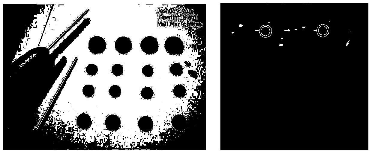
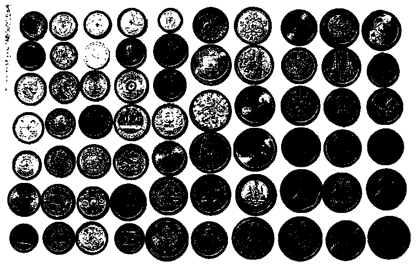
[0061] According to the method of the present invention, at first utilize Matlab or C language to write circular target detection program; Then in various scenes that need to detect circular target installation acquisition camera collects original image; Then the image that gathers is input into circular target as source data It is processed in the target detection program; after boundary point extraction, voting line calculation, probability pair voting and parameter search, the position and size of the circular object in the input source image can be obtained. The method of the present invention can be used for circular objects in natural scenes.


PUM


Abstract

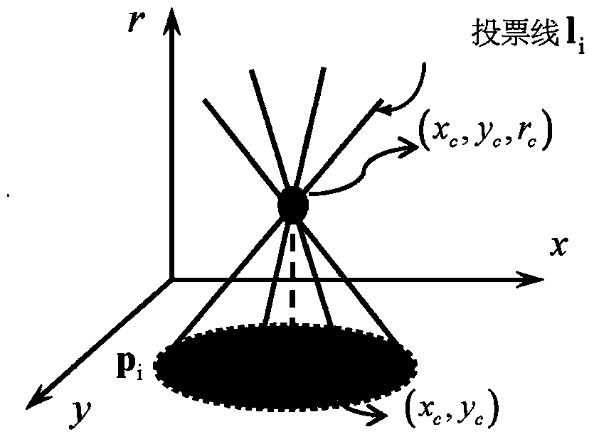
The invention discloses a circular target detection method based on voting line clustering, belongs to the technical field of computer vision and in particular relates to an image target detection technology. The method comprises establishing voting lines in a parameter space by use of the gray scale gradient direction of boundary points, and finding out the point having the maximum voting line density as the optimal circular parameter. According to the modeling manner, the optimal parameter can be quickly obtained by use of a probability density estimation method in a continuous parameter space, and therefore, the accuracy of circular target detection is improved and the detection efficiency is also guaranteed.

Description

technical field [0001] The invention belongs to the technical field of computer vision and relates to target detection technology in images. Background technique [0002] Target detection is one of the hot research issues in the field of computer vision in recent years. It refers to accurately and quickly finding targets with certain characteristics in various images, which is an important basis for realizing computer vision and artificial intelligence. Among them, circular object detection is an important research problem in this field, and its wide applications include circular object detection in natural scenes, human eye positioning in face recognition, and circular workpiece detection in industrial automation. Existing circle detection methods mainly include two categories: 1. Circle detection methods based on maximum likelihood estimation and 2. Circle detection methods based on voting. [0003] The circular target detection method based on maximum likelihood estimati...

Claims


Application Information

Patent Timeline
Patent Type & Authority Applications(China)
IPC IPC(8): G06T7/00
CPCG06V10/44G06V10/752G06V2201/07
Inventor 潘力立
Owner UNIV OF ELECTRONICS SCI & TECH OF CHINA
Learn More