
Continuity test device and continuity test method of airborne cable

A continuity test and cable technology, applied in the field of the continuity test device for airborne cables, can solve the problems of relying on labor, cumbersome steps, low efficiency, etc.

Inactive Publication Date: 2015-02-04
BEIJING JINGWEI HIRAIN TECH CO INC
View PDF9 Cites 5 Cited by
  • Summary
  • Abstract
  • Description
  • Claims
  • Application Information

AI Technical Summary

Problems solved by technology

And because the connectors at both ends of the airborne cable may be far away, some test equipment used on the airborne cable production line cannot be used for testing. The existing test method is that two testers are a group, using long wires, batteries , indicator lights form a simple circuit, two people are respectively located at both ends of the installed airborne cable, connect the two ends of the long wire to the same wire core in the aviation connector at both ends of the airborne cable, and then communicate and confirm through the walkie-talkie Whether the indicator light is on, to manually test whether the end-to-end path of the airborne cable is normally conducted
[0004] However, there are at least the following problems in the prior art: the airborne cables of the entire aircraft have thousands of wire cores, and it is a huge task to conduct all the conduction tests, and the existing airborne cable testing methods rely entirely on manual work. , low efficiency, cumbersome steps, and low reliability of test results

Method used


Image

  • Continuity test device and continuity test method of airborne cable
  • Continuity test device and continuity test method of airborne cable
  • Continuity test device and continuity test method of airborne cable

Examples


Embodiment 1

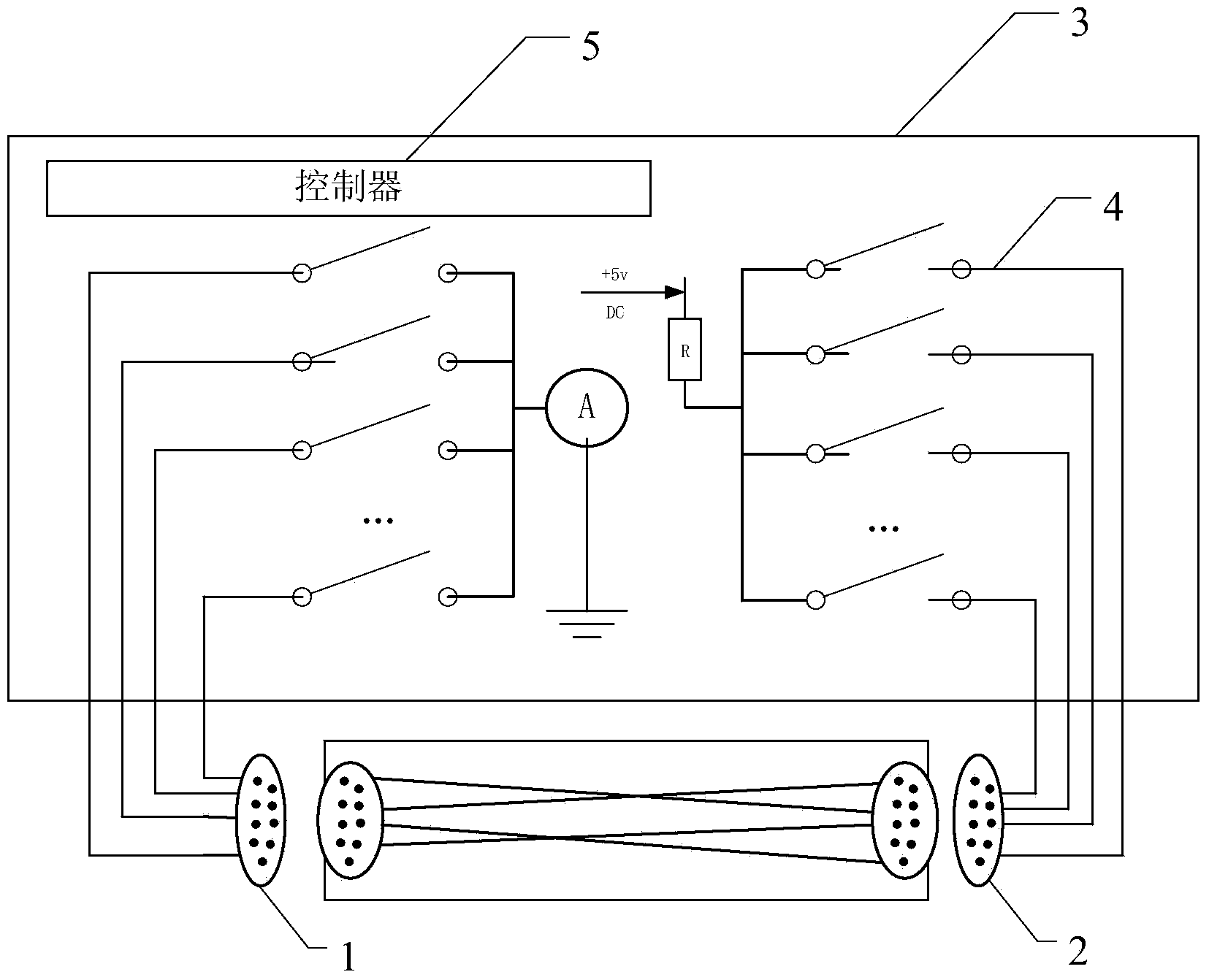
[0035] figure 1 It is a schematic structural diagram of an airborne cable conduction test device provided in this application.

[0036] refer to figure 1 As shown, the conduction test device of the airborne cable in the embodiment of the present application is used to perform a conduction test on the airborne cable after the final assembly, including:

[0037] Output connector 1, input connector 2 and test host 3;

[0038] In the embodiment of the present application, the continuity test device provides a test cable, an output terminal connector, and an input terminal connector that are matched with the cable connector of the airborne cable to be tested, so that after the deployment of the airborne cable to be tested is completed, Inserting the output end connector and the input end connector into the cable connectors at both ends of the airborne cable to be tested realizes end-to-end connection and testing of the test cable and the airborne cable to be tested. At this time...

Embodiment 2

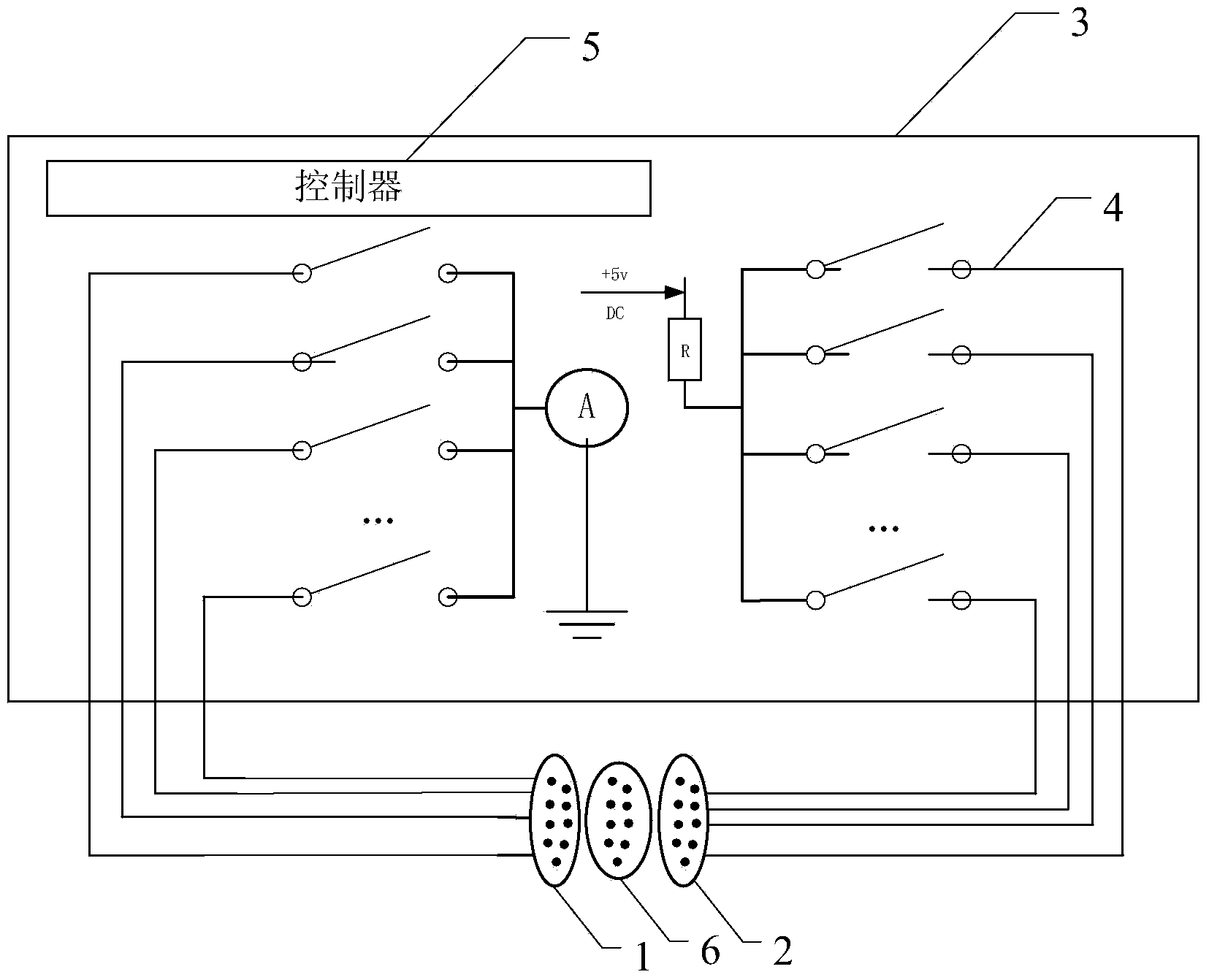
[0049] figure 2 It is a schematic structural diagram of another airborne cable conduction test device provided in this application.

[0050] refer to figure 2 As shown, the conduction test device of the airborne cable provided by the embodiment of the present application includes:

[0051] Output connector 1, input connector 2, self-test connector 6 and test host 3;

[0052] The output connector 1 and the input connector 2 can be respectively connected to the cable connectors at both ends of the airborne cable to be tested, and the multiple core wires in the output connector 1 are connected to the The multiple core wires in the airborne cable correspond one-to-one, and the multiple core wires in the input connector 2 correspond to the multiple core wires in the airborne cable to be tested;

[0053] The test host 3 is provided with multiple test circuits 4 and controllers 5;

[0054] Each test circuit 4 is composed of an output terminal, a relay, a power module, a test re...

Embodiment 3

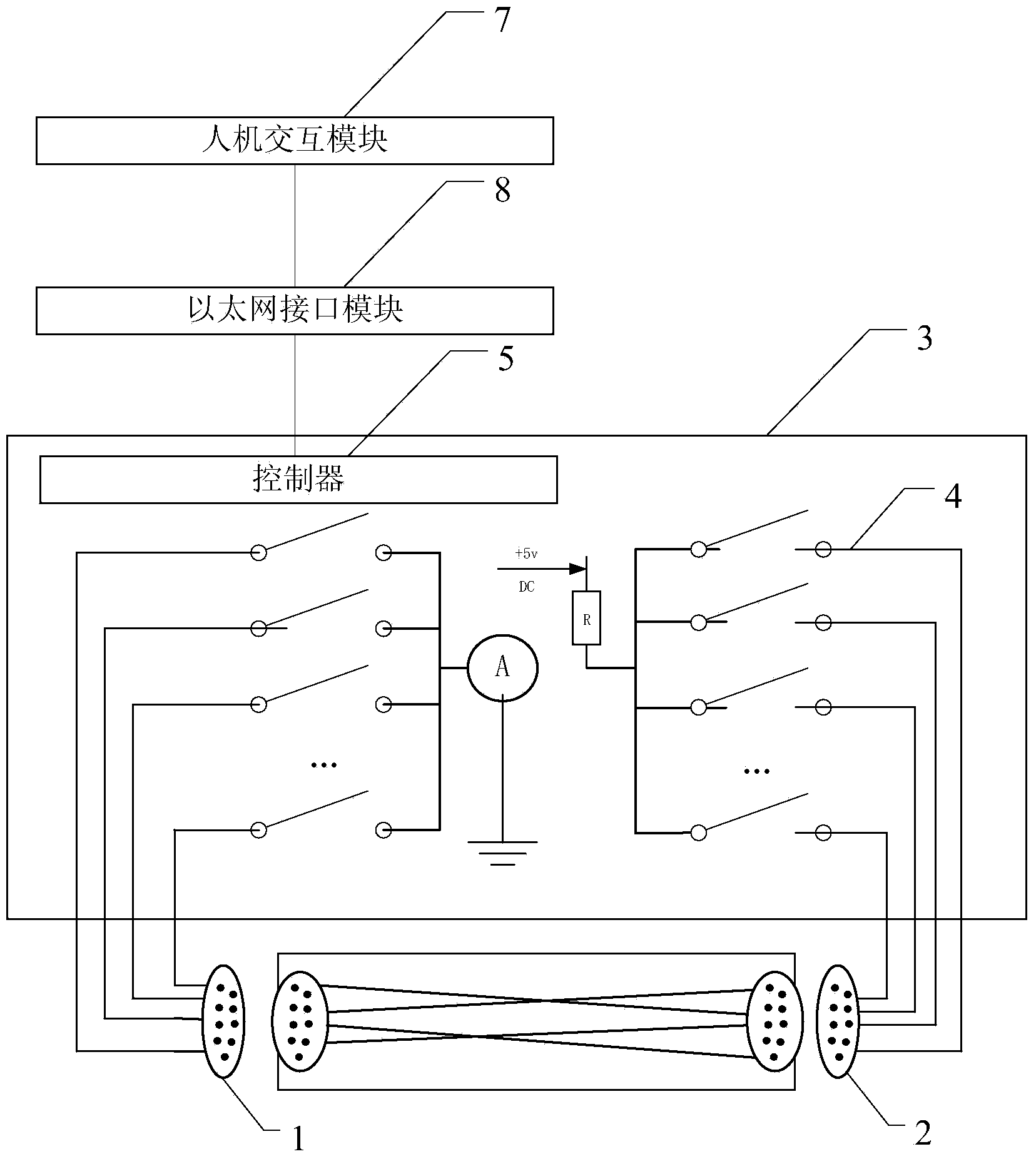
[0062] image 3 It is a schematic structural diagram of another test device for continuity of an airborne cable provided by the present application.

[0063] refer to image 3 As shown, the conduction test device of the airborne cable in the embodiment of the present application is used to perform a conduction test on the airborne cable after the final assembly, including:

[0064] Output connector 1, input connector 2 and test host 3;

[0065] The output connector 1 and the input connector 2 can be respectively connected to the cable connectors at both ends of the airborne cable to be tested, and the multiple core wires in the output connector 1 are connected to the The multiple core wires in the airborne cable correspond one-to-one, and the multiple core wires in the input connector 2 correspond to the multiple core wires in the airborne cable to be tested;

[0066] The test host 3 is provided with multiple test circuits 4 and controllers 5;

[0067] Each test circuit 4 ...


PUM


Abstract

The invention discloses a continuity test device and a continuity test method of an airborne cable for continuity test of the airborne cable after final assembly. When a controller in the continuity test device of the airborne cable starts a continuity test, the controller controls the starting and stopping of relays in multiple test circuits according to a preset sequence, so that just one relay is located in a closed state at the same time and whether a loop current exists in the test circuit in which the closed relay exits is detected, If so, a core wire which is connected with the test circuit at which the closed relay exists in the to-be-tested airborne cable is connected, otherwise, the core is not connected. Thus, the controller can control the multiple test circuits connected with the core wires in the to-be-tested airborne cable to connect in turn to sequentially judge the continuity condition of the core wires in the to-be-tested airborne, so that a fast, simple and highly reliable automatic continuity test is carried out on the airborne cable under the limited condition that the airborne cable is already installed and deployed on an aircraft.

Description

technical field [0001] The present application relates to the field of circuit technology, in particular to a device and method for conducting a test of an airborne cable. Background technique [0002] In the final assembly stage of the aircraft, after the airborne cables are installed and deployed on the aircraft, the onboard cables need to be tested for continuity to ensure that the installed airborne cables are not damaged before they are connected to the airborne equipment. [0003] According to the general assembly process, the airborne cables will be deployed and fixed inside the aircraft fuselage first, and then the continuity test and insulation test will be performed. At this time, since the cables have been deployed and installed, the position is fixed and cannot be moved, so only the end-to-end complete path is performed. test. And because the connectors at both ends of the airborne cable may be far away, some test equipment used on the airborne cable production ...

Claims


Application Information

Patent Timeline
Patent Type & Authority Applications(China)
IPC IPC(8): G01R31/02
Inventor 邓郡
Owner BEIJING JINGWEI HIRAIN TECH CO INC
Learn More