
Printing plate temperature control device for waterless offset printing

A temperature control device, waterless offset printing technology, applied in general parts of printing machinery, printing, printing presses, etc., can solve the problems of low ink viscosity, difficulty in regulating the temperature of cooling liquid, and increase in ink temperature, so as to ensure the printing quality, Good print quality with low sealing requirements

Inactive Publication Date: 2015-02-04
BEIJING INSTITUTE OF GRAPHIC COMMUNICATION
View PDF7 Cites 6 Cited by
  • Summary
  • Abstract
  • Description
  • Claims
  • Application Information

AI Technical Summary

Problems solved by technology

[0002] During the working process of waterless offset printing equipment, it is necessary to control the surface temperature of the printing plate cylinder, otherwise, the temperature of the ink will rise due to the pressure of the ink delivery system on the roller, which will cause the ink to be coated on the printing plate due to If the temperature is too high, the viscosity is too low, and the paste failure occurs
In the prior art, the commonly used method is to set an ink shifting roller device with a hollow structure, inject cooling liquid into the cavity of the ink shifting roller, and realize the alignment of the printing plate through the counter-rolling between the ink shifting roller and the printing plate cylinder. The ink on the surface of the cylinder is cooled to achieve the purpose of temperature control on the surface of the printing plate, but the control of this method is complicated, and it is also quite difficult to control the temperature of the cooling liquid, and the temperature control effect is not good, and it is also difficult to meet the temperature control on the surface of the printing plate. Two-way temperature control requirements for cooling and heating

Method used


Image

  • Printing plate temperature control device for waterless offset printing

Examples


Embodiment Construction

[0012] In order to make the object, technical solution and advantages of the present invention clearer, the present invention will be further described in detail below in conjunction with specific embodiments and with reference to the accompanying drawings.

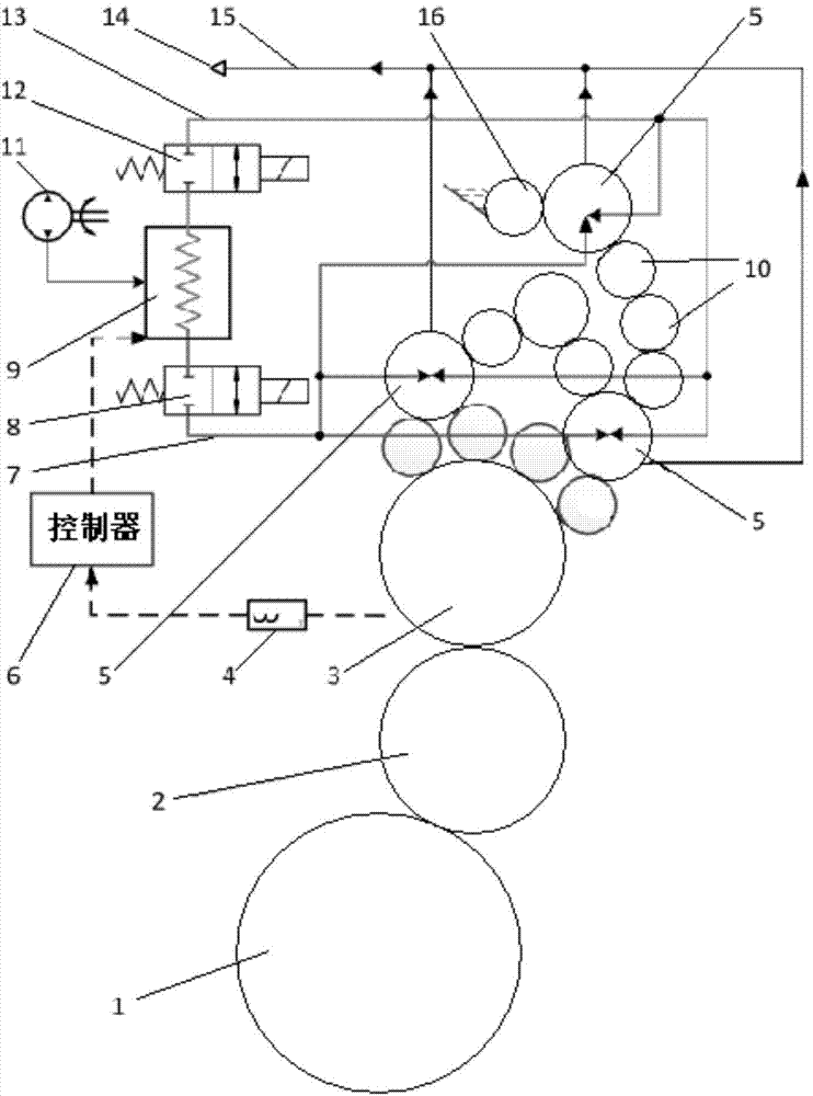
[0013] refer to figure 1 , is a schematic structural diagram of a printing plate temperature control device for waterless offset printing according to an embodiment of the present invention.

[0014] The embodiment of the present invention provides a printing plate temperature control device for waterless offset printing, which includes a vortex tube 9 for generating cold and hot air flow, and the hot flow end is provided with a device for adjusting the temperature and flow rate of the output air flow at the cold flow end and the hot flow end. The regulating valve; the device of this embodiment also includes a temperature sensor 4, a controller 6 and at least one temperature-controlled ink roller 5; the temperature-contro...


PUM


Abstract

The invention discloses a printing plate temperature control device for waterless offset printing. The device comprises a vortex tube used for generating cold and heat air flows, wherein a heat flow end of the vortex tube is provided with an adjusting valve which is used for adjusting the temperature and flux of the air flows output from a cold flow end and the heat flow end. The device is characterized by further comprising a temperature sensor, a controller and at least one temperature control ink roller, wherein the temperature ink roller is arranged between an ink fountain roller and a printing plate cylinder of a waterless offset printing machine; the cold flow end and the heat flow end of the vortex tube are respectively connected to the temperature control ink roller by a pipeline; a first stop valve is arranged at the upstream of the pipeline connected with the cold flow end; a second stop valve is arranged at the upstream of the pipeline connected with the heat flow end; the temperature sensor is used for detecting the surface temperature of the printing plate cylinder of the waterless offset printing machine, and transmits the temperature to the controller; the controller generates a control signal according to a predetermined proper printing temperature range to control the actions of the adjusting valve, the first stop valve and the second stop valve. The printing plate temperature control device for waterless offset printing disclosed by the invention is simple in structure and highly efficient in control.

Description

technical field [0001] The invention relates to the field of printing equipment, in particular to a printing plate temperature control device for waterless offset printing. Background technique [0002] During the working process of waterless offset printing equipment, it is necessary to control the surface temperature of the printing plate cylinder, otherwise, the temperature of the ink will rise due to the pressure of the ink delivery system on the roller, which will cause the ink to be coated on the printing plate due to If the temperature is too high, the viscosity will be too low, and paste failure will occur. In the prior art, the commonly used method is to set an ink shifting roller device with a hollow structure, inject cooling liquid into the cavity of the ink shifting roller, and realize the alignment of the printing plate through the counter-rolling between the ink shifting roller and the printing plate cylinder. The ink on the surface of the cylinder is cooled t...

Claims


Application Information

Patent Timeline
Patent Type & Authority Applications(China)
IPC IPC(8): B41F31/10B41F31/02B41F7/20
Inventor 柴承文王仪明武淑琴
Owner BEIJING INSTITUTE OF GRAPHIC COMMUNICATION
Learn More