
Buoy type filter

A filter and buoy type technology, which is applied in the field of sewage treatment, can solve the problems of shortening the service life of thick and short filters, complicated dirt, and reducing the passing speed of sewage, so as to achieve the effect of maintaining filtration efficiency, good filtration effect, and self-cleaning

Inactive Publication Date: 2015-02-04
NANJING AEROSUN MORITA ENVIRONMENTAL PROTECTION S&T
View PDF4 Cites 1 Cited by
  • Summary
  • Abstract
  • Description
  • Claims
  • Application Information

AI Technical Summary

Problems solved by technology

However, the coarse filter directly contacts the untreated sewage, and it is very easy to accumulate impurities on the surface, thereby reducing the passing speed of the sewage; at the same time, because the dirt accumulated in the coarse filter is very complicated to clean, the service life of the coarse filter is also shortened.

Method used


Image

  • Buoy type filter
  • Buoy type filter
  • Buoy type filter

Examples


Embodiment 1

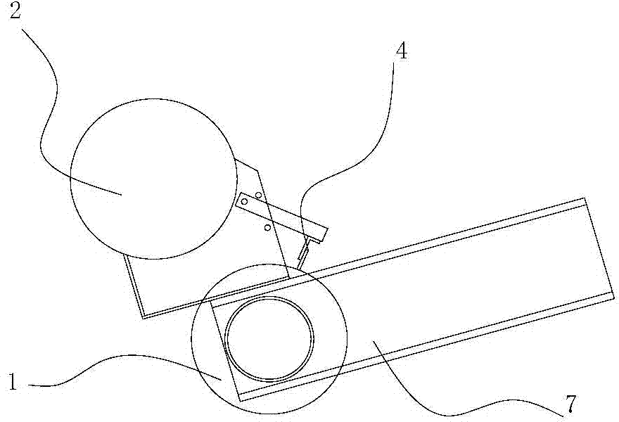
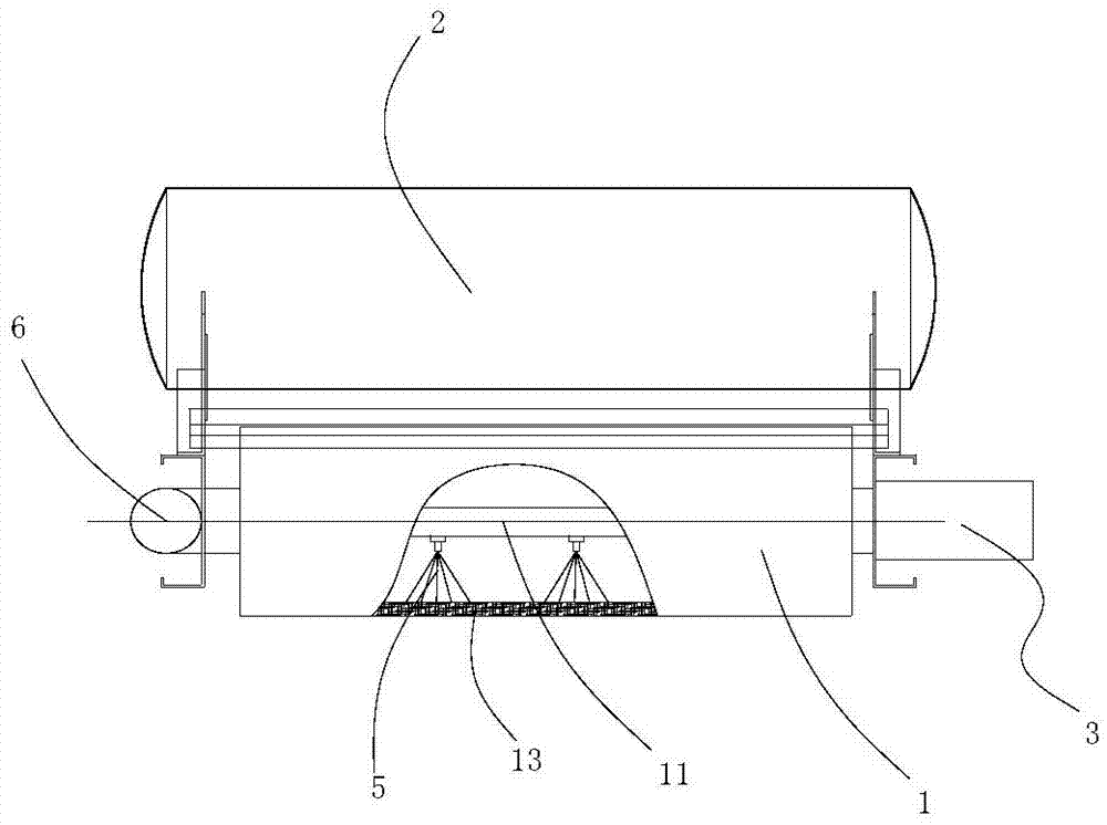
[0015] Such as figure 1 and figure 2 As shown, the buoy filter of the present embodiment includes a sieve drum 1, a power source 3, a buoy 2 and a fixed plate 7, and the buoy 2, the power source 3 are all fixedly connected to the fixed plate 7; the sieve drum 1 is installed on the fixed plate and Driven by a power source to rotate, the sieve drum 1 is a hollow cylinder, and the outer wall of the sieve drum 1 is provided with a number of filter holes, all the filter holes form a filter net 13, and the side of the sieve drum 1 is provided with a water outlet 6.

[0016] In this embodiment, the power source 3 adopts a motor, of course, the power source 3 may also adopt other transmission mechanisms such as a rack and pinion or a pulley.

[0017] Usually large impurities in water are deposited below the sewage. In this embodiment, the buoyancy of the buoy 2 is used to ensure that the sieve drum 1 filters the clearer sewage in the upper layer, which contains less impurities, whic...

Embodiment 2

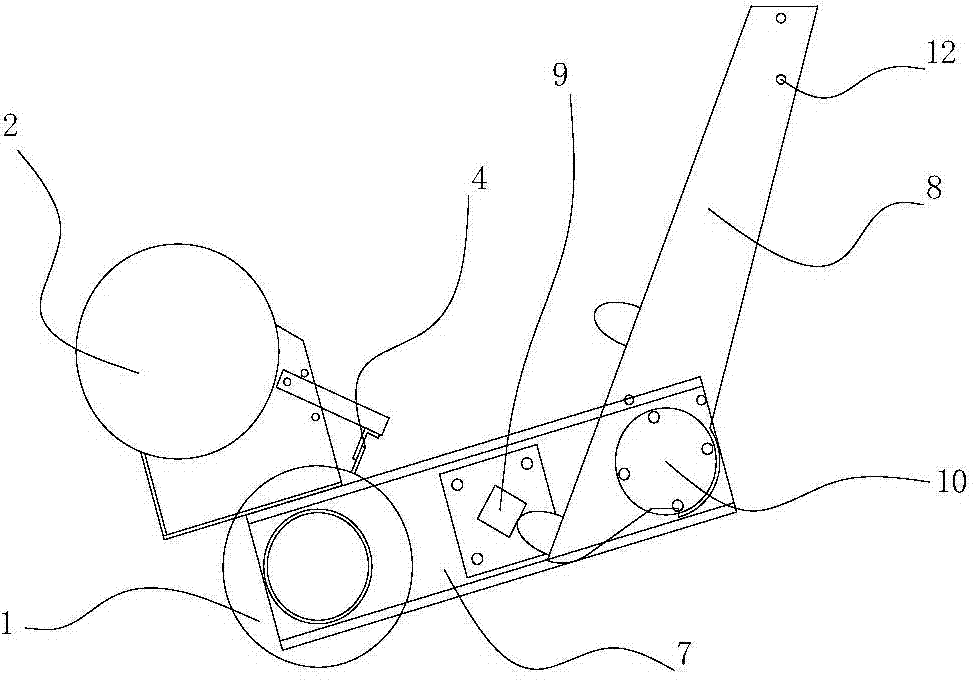
[0022] This embodiment is an improvement on the basis of Embodiment 1, and the difference from Embodiment 1 is that: image 3 As shown, the screen drum 1 and the buoy 2 are located at one end of the fixed plate 7, and the other end of the fixed plate 7 is hinged with a mounting plate 8, namely image 3 The mounting plate 8 shown in the figure can rotate around the rotating shaft 10; the fixed plate 7 is provided with a limit block 9, and the end of the mounting plate 8 close to the screen drum 1 is offset against the limit block 9. In this way, the relative position of the buoy 2 and the screen drum 1 remains unchanged, and at the same time, the two relative to the fixed position can be adjusted within a certain height range around the rotating shaft 10 under the action of buoyancy.

[0023] In this embodiment, an installation hole 12 for installing a counterweight can also be provided at the end of the installation plate 8 away from the screen drum 1, so that the height of th...


PUM


Abstract

The invention relates to a buoy type filter and belongs to the technical field of sewage treatment. The filter comprises a sieving drum, a power source, a buoy, a scraping plate, a cleaning pipe and a fixed plate, wherein the buoy, the power source, the scraping plate and the cleaning pipe are respectively and fixedly connected with the fixed plate; the sieving drum is arranged on the fixed plate and is driven to rotate by the power source; the sieving drum is a hollow cylinder; the outer wall of the sieving drum is provided with a plurality of filtering holes which form a filtering net; a water outlet is formed in the side surface of the sieving drum; one end of the scraping plate is fixedly connected on the fixed plate, and the other end of the scraping plate is close to the peripheral surface of the sieving drum; the cleaning pipe is connected with a high-pressure water source, is fixedly connected with the fixed plate and is inserted into the sieving drum; the part of the cleaning pipe, which is inserted into the sieving drum, is provided with a spraying nozzle communicated with the cleaning pipe; and the water spraying direction of the spraying nozzle faces to the filtering net. The buoy type filter has the advantages that not only is the filtering effect good, but also stains are not easy to be stacked.

Description

technical field [0001] The invention relates to a buoy filter, which belongs to the technical field of sewage treatment. Background technique [0002] At present, when treating sewage with large sludge content, in order to protect the more sophisticated purification device, the sewage must be pretreated through a coarse filter. However, the coarse filter directly contacts the untreated sewage, and it is very easy to accumulate impurities on the surface, thereby reducing the passing speed of the sewage; at the same time, because the dirt accumulated in the coarse filter is very complicated to clean, the service life of the coarse filter is also shortened. Contents of the invention [0003] The object of the present invention is to overcome the above-mentioned defects in the prior art and provide a filter with good filtering effect, not easy to accumulate dirt and long service life. [0004] In order to solve the above technical problems, the technical solution proposed by ...

Claims


Application Information

Patent Timeline
Patent Type & Authority Applications(China)
IPC IPC(8): B01D33/073B01D33/46B01D33/50
Inventor 居灿华刘召杰吕晓媛
Owner NANJING AEROSUN MORITA ENVIRONMENTAL PROTECTION S&T
Learn More